background image

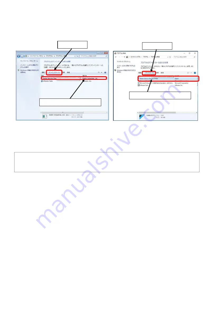
3) Select Daikin Service Checker TYPE4 and click Uninstall

After this point, uninstall process will start. This process is same for Windows7 and 10.
Please carry out uninstallation process by following instruction.
(Please follow instructions for the OS other than Winsows7 and 10)

1. Select Daikin Service Checker TYPE4

2. Click Uninstall

2. Click Uninstall

1. Select Daikin Service Checker TYPE4

(Note)
* Even if the software will be removed, recorded data will remain.

You can utilize them once you’ll install the 

software. 

AS0112-P-DENV

14

https://daikin-p.ru

Summary of Contents for TYPE4 Checker

Page 1: ...TYPE4 Checker Instruction Manual Global Service Department June 2019 AS0112 P DENV 0 https daikin p ru ...

Page 2: ... the checker software function 18 Chapter 5 Recording operation data 19 5 1 Viewing operation data 19 5 1 1 Customer info selection 19 5 1 2 Network map display 22 5 1 3 Switching modes 24 5 1 4 Detailed info input 26 5 1 5 Operation data display 28 5 2 Recording setup 32 5 2 1 Setup recording 32 5 3 Centralized operation 34 Chapter 6 Playback of recorded operation data 36 6 1 Playing operation da...

Page 3: ...rious damage to equipment are marked as CAUTION The contents of this document could be updated without precautions The contents of this document is not allowed to reprint without permissions Functions ways to use this software and supported VRV models by this software are different based on software version In this document instructions are targeted at V1 2 1 1 or later version PC software for TYP...

Page 4: ...YPE4 checker software for supporting newly introduced products 3 Purpose Troubleshooting diagnosis of VRV systems supporting diagnosis by visualized operation data Commissioning of VRV systems checking number of connected indoor units operation condition check 4 How to obtain TYPE4 checker box This tool is distributed as service part from local affiliate distributor of Daikin Please contact your l...

Page 5: ...ed in the TYPE4 package D3 NET connection port Connection port for D3 NET communication cable This is not for power supply terminal please do not apply power line If you connect power supply to this port TYPE4 Checker box will be broken and burnt 5 TYPE4 checker details Main switch D3 NET connection port USB2 0 port Type B For communication with Windows PC or power supply by PC USB port or AC adap...

Page 6: ...2 USB cable Connection cable for connecting Checker and PC USB Type B USB Type A standard USB cable 1 2 Preparation 1 2 1 Essential materials Preparations for materials to be necessary for VRV operation data recording will be explained in this section 1 2 1 Essential materials TYPE4 checker 1 2 2 D3 NET cable AS0112 P DENV 5 https daikin p ru ...

Page 7: ...n case of use circular shaped wire terminal please select wire terminal which fits this terminal block For control signal wiring use vinyl cords or cables with two core and sheathed as follow Vinyl cabtyre cylindrical cord VCTF JISC3306 Vinyl insulated vinyl sheathed cable for control CVV JISC3401 Vinyl insulated vinyl sheathed cylindrical cable for control CVS JISC3401 Vinyl insulated vinyl sheat...

Page 8: ...ware Back USB 2 0 terminal Type B PC Checker box Connect PC and Checker by the USB cable included in the Checker package B connector A connector USB cable included 3 Confirmation of connection To avoid troubles such as PC and Checker connection please check connection between PC and Checker as instructions listed below How to confirm Connection check can be done without connecting checker and VRV ...

Page 9: ...e go back exit once and check COM port setting in option menu Then please check again Supported model list In HELP menu of Checker software 2 Select COM port to be used in Select Port window 3 Click OK button to proceed Click top box and select COM port number to use Please select COM port number which shows Silicon Labs CP210x USB to UART Bridge in the 2nd box COM port number is different from PC...

Page 10: ...oftware to check operation data of new model AS0112 P DENV 9 2 2 Installation procedure 1 Please download from Daikin Business Portal and execute installation file on your PC folder 2 Installer program will start If NET Framework 4 6 2 or higher is not installed in your PC installation of NET Framework 4 6 2 will start If it is already installed move to 4 Please click Accept button to proceed If a...

Page 11: ...alled to the below folder 32bit OS C Program Files Daikin Checker4 64bit OS C Program Files x86 Daikin Checker4 To change installation folder please install after change the system setting If you do not have the administrator rights installation might not be executed Please consult with your PC administrator such as IT department for further support 6 Click Next button to proceed If above screen w...

Page 12: ...nder Daikin folder and desktop Left picture is a sample of Windows7 PC Looks of start menu display could differ from Windows version and PC situation 7 When installation started wait for the completion 8 Installation completed AS0112 P DENV 11 https daikin p ru ...

Page 13: ... shown Select Remove and press Finish If above screen will be shown press Yes to proceed 11 Software will be removed 12 Software has been removed Note Even if the software will be removed recorded data will remain You can utilize them once you ll install the software AS0112 P DENV 12 https daikin p ru ...

Page 14: ... is not installation file in your PC It is easier to uninstall from installer file for update Procedure will be explained in below procedure with Windows7 and Windows10 sample Procedure 1 Select Control panel of Windows Windows7 Windows10 2 Select Control panel under Windows System 1 Click Start button 2 Double click Program Double click Program 1 Click Start button 2 Select Control panel Double c...

Page 15: ...ation process by following instruction Please follow instructions for the OS other than Winsows7 and 10 1 Select Daikin Service Checker TYPE4 2 Click Uninstall 2 Click Uninstall 1 Select Daikin Service Checker TYPE4 Note Even if the software will be removed recorded data will remain You can utilize them once you ll install the software AS0112 P DENV 14 https daikin p ru ...

Page 16: ...rminal of VRV outdoor unit or indoor unit or centralized controller If it would be connected to power terminal there is a possibility of fatal accident by electric shock or damage of the unit Caution 1 It s not necessary to correspond F1 F2 of the transmission terminal of VRV to F1 F2 of the checker like F1 F1 or F2 F2 respectively no polarity 2 Recommended connection point of VRV unit is F1 F2 te...

Page 17: ...or example if you connect Checker in main bus operation data of VRV systems in branch bus cannot be monitored If Wiring Adaptor for Electrical Appendices 1 or 2 KRP2A or KRP4A are installed to the same D3 NET line an error will be displayed to BMS or other centralized control system To avoid this error it is necessary to prohibit centralized control function of checker software see 7 3 2 Prohibit ...

Page 18: ...checker software Windows 7 Windows 10 2 Select Daikin Service Checker TYPE4 under Daikin folder 2 Select Daikin Service Checker TYPE4 1 Click Start button 1 Click Start button 2 Checker software starts up and shows the main menu shown left It looks same for both Windows7 and 10 4 2 Quit the checker software There are two ways to quit checker software 1 Click X button on the top right corner AS0112...

Page 19: ...ing importing recorded data or customer information to from other users or PC Refer to Chapter 7 1 Customer data Use for enter edit customer information please enter customer info for all the time Saved network map information can be checked here Refer to Chapter 7 2 and 6 2 4 3 Overview of the checker software function There are buttons listed below are in the checker software main menu AS0112 P ...

Page 20: ...ng can be executed without entry of customer information Record only Click Record button By Record menu VRV operation data monitoring and recording collecting data can be executed It is necessary to use this menu if case of only monitoring operation data without recording As shown in the right chart data is managed as tree structure From the top data is categorized as customer network map system a...

Page 21: ...mer information to avoid unnecessary system stand by To delete existing customer please press Delete customer button To return to main menu please press Back button in the bottom left corner 3 Customer data input screen Please enter customer information Customer ID is mandatory field Customer name is used in Operation data selection screen so please use clear name For the other items please enter ...

Page 22: ...ork map name mandatory 2 After entering appropriate network map name please press OK button to proceed Network map display screen Then proceed to 5 1 2 Network map display Please press Back button to return Note 1 By pressing OK button of 6 Edit map name screen system will be in stand by status and will be thermostat off for several minutes 2 If you use existing network map which was created befor...

Page 23: ...rded data could be mixed up and would not be recorded correctly To avoid such an issue please do not change date time of your PC during recording the data Note1 Without initialization of D3 NET line after adding removing outdoor unit indoor unit BS unit or replacing control PCB network map cannot be shown In those cases please carry out D3 NET initialization before using checker In case of system ...

Page 24: ...nutes system is in this status during auto scan 2 If it is not possible to display all units or system in one screen please press System or System button in the bottom left corner in the screen to move the screen in vertical direction Note 1 If the color of icon is white units are under detection Operation data would not be displayed until completion of unit detection period will end Please wait f...

Page 25: ...ss in case of addition removal of the units or replacement of control PCB Network map information will be acquired again to update Note Units on the same D3 NET line will be in stand by status thermostat off for several minutes Please be aware of that After completion of this sequence system will resume automatically B Display mode Display mode Disp op data Disp Q ty Disp op data Proceeding to Ope...

Page 26: ...a recording to PC data drive Please proceed to 5 2 1 Setup PC recording Periodic record start By pressing this button data recording to PC drive will start On the upper left screen Period Rcd sign will be indicated Button will change to Period rec end by pressing the button again to stop recording AS0112 P DENV 25 https daikin p ru ...

Page 27: ...rovide unit model name Rough category of product is pre set To provide more details please select from list or enter info manually Indoor unit does not have pre set names so please enter name manually Centralized address To provide centralized group number Automatically acquired only during making new map You can enter manually Auto address not allowed to change Automatically acquired In Network m...

Page 28: ...e is a sample of re arrangement of detailed info of I 1 and I 2 2 Select I 2 which is destination and press Copy button detailed info of I 2 will move to I 1 1 Select I 1 2 Press List display 2 Press Copy button 1 Select detailed info of I 2 3 Press Cancel esc button to return to Detail Data Input screen 5 After finishing input please press Cancel esc button to return to Network map display screen...

Page 29: ...h lower left In case of ON status blue bar is shown Number of each bar corresponds to the number of each parameter of present value chart Up to 8 items per unit can be displayed You can jump to the other unit in the same system 1 Analog data graph 4 Inspection sheet display Note About cursor vertical line in the graph 1 To display operation data from record mode cursor is not displayed initially T...

Page 30: ...m name are displayed Data Operation data value is shown In case of D3 NET connection data refresh interval is in several minutes 1 5 min Last modified Time of data updated is shown In case of D3 NET some are updated in several minutes interval Full scale The value of 100 scale of each analog data Per unit 8 analog data and 8 digital data can be displayed in the graph Please select a desired parame...

Page 31: ...g O 2 outdoor unit 2 Data time Time of data acquired in Operation data display graph 4 4 Manual input box Data box in pink background is required to enter select manually After clicking once you can enter necessary values 4 5 Select judgment result For judgment result area you can select and put circle by clicking YES or NO Values cannot be entered manually YES NO selection only Note About the pos...

Page 32: ...ata display screen will be reflected By clicking you can enter values manually 4 7 Switch between outdoor units Inspection sheet per outdoor unit will be displayed You can switch between outdoor unit by selecting tab 4 8 Supported model May 2019 AS0112 P DENV 31 5 By pressing X button in the upper right corner return to Operation data display screen VRV3 HP HR Q W S VRV4 HP HR Q W S i VRV5 VRV A X...

Page 33: ...fy how to stop recording Manual Recording continues until Period rec end button is pressed Auto Recording will end after the time specified in Recording time box Please enter recording time in minutes 3 Record system select It is possible to select record not record by system basis You can select multiple systems Select check box for each corresponding system and click to check uncheck 3 Set recor...

Page 34: ... Checker box Communicating Error will be shown Please check connection and retry recording Period Rcd Changed to Period rec end 3 To start periodic record to PC data drive press Period rec start button in Network map screen Period Red sign will be indicated in the upper left corner Besides button will be changed to Period rec end Press Period rec start button Communicating Error display AS0112 P D...

Page 35: ...e button Centralized operation screen In this screen indoor unit which can be controlled centrally are listed as icon in the order of centralized group number Icon color will change based on the status Color Status Red Error Violet Comm Error Green Running Gray Stop Note If the centralized group number is not set yet it is necessary to set them Connect TYPE4 checker box to D3 NET line and setup cu...

Page 36: ...s indicated as remote controller shows Under center control Master centralized controller does not allow slave controller No centralized operations can be done by checker Under forced stop Under status of forced stop control No centralized operations other than stop command by checker Under centralized control If other centralized controller has prohibited the operations of indoor units from manua...

Page 37: ...ata selection screen 2 Please select desired operation data and highlight Disp op data Showing operation data please proceed to 3 CSV data output Exporting csv format data please proceed to 6 3 CSV output Delete Removing operation data Back Return to main menu Select desired data to open Press Play button AS0112 P DENV 36 https daikin p ru ...

Page 38: ...e scale Proceed Move timeline to forward 50 of X axis time scale Left Move cursor vertical line to the left Right Move cursor vertical line to the right 4 Max Min value of analog data and error code can be searched digital data cannot be searched Present value list in the right click to highlight desired data item and press Search button 1 Analog data Enter search threshold value Button 2 Press Se...

Page 39: ...heet can be created by pressing button in the bottom of this screen 6 By pressing Back button to customer data selection screen Please refer to 5 1 5 Operation data display for details of inspection sheet AS0112 P DENV 38 https daikin p ru ...

Page 40: ... in PC Procedure 1 In main menu press Customer data button to proceed to Customer selection screen 2 Customer selection screen Press Select customer button to proceed to Network map selection screen 3 Network map selection screen Select desired map and press OK button to proceed to Network map display screen Press Select customer button 2 Press OK 1 Select desired map Press Customer data button AS...

Page 41: ...reen System System Move between systems Detail Data Input Press in case of model installation place info input Please proceed to 5 1 4 Detailed info input Back Return to Network map selection AS0112 P DENV 40 https daikin p ru ...

Page 42: ...main menu press Play button to Customer data selection screen 2 Customer data selection screen Select desired data and press CSV data output button 1 Select data 2 Press CSV data output button 3 CSV output setting screen After output data period header data relevant settings press OK button to proceed After settings press OK button Press Play button AS0112 P DENV 41 https daikin p ru ...

Page 43: ...ct location to save and enter file name then press Save button 1 Select location to save 2 Enter file name 3 Press Save button Note 1 CSV file will be exported 1 file per unit both outdoor indoor For example the system with 1 outdoor unit and 8 indoor unit 1 csv file for outdoor unit and 8 csv files for indoor units will be exported 2 If recorded period is too long to store all data in one csv fil...

Page 44: ...ssible to select folder name Unit of transferring data is 1 Operation data and customer info 2 Customer info only Network map information is included in customer information Press Data transfer button Chapter 7 Other functions 1 In main menu press Data transfer button to proceed to Data transfer screen Note Data can be copied directly from PC folder location by Windows explorer it is not easy to l...

Page 45: ...e as 1 Transfer operation data and customer information 3 Press Cancel button to exit Exporting data to storage media 1 Select operation data or customer information on the left to transfer 2 Select destination folder in the right side of the screen 3 By pressing right arrow button to start transferring Importing data from storage media or folder 1 Select operation data or customer data informatio...

Page 46: ...a selection screen etc It is highly recommended to enter 5 Other items are entered based on their necessities they are not mandatory fields 6 After finishing entry press Save button Return without saving press Cancel button Note Other than Customer data menu customer information can be entered from Record menu Checker software manages operation data by customer basis Therefore customer ID is manda...

Page 47: ...COM port to use 3 Press OK button to save changes Click the top box list and select COM port from listed port number From listed COM port numbers please select COM port number which comes with Silicon Labs CP210x USB to UART Bridge in the middle box Note In case of no COM port with Silicon Labs CP210x USB to UART Bridge It is necessary to install driver files of USB serial port Please obtain appro...

Page 48: ...ion to obtain unit information in case of connecting checker to systems for the first time at first temporarily permit centralize operation and create a new network map Then prohibit centralized control again It is possible to stop sending centralized control command from checker by this setting Checker has a centralized operation function it regularly transmits data as a centralized controller to...

Page 49: ... switched in between Japanese English and Simplified Chinese Change will take effect after restarting the software By change of language some units could not be correctly monitored due to model info incompatibility Change GUI language from Settings Language AS0112 P DENV 48 7 3 4 Change display unit of measure temperature pressure Unit of measure temperature pressure can be selected from Celsius k...

Page 50: ...tion guide Show wiring guidance screen to show how to connect TYPE4 checker and VRV 3 Support models Supported model list can be checked by PDF file 4 Version Software version Showing how to connect TYPE4 checker to VRV 2 Connection guide 1 Help Help Showing help manual screen AS0112 P DENV 49 https daikin p ru ...

Page 51: ...Software version can be checked 4 Version info 3 Supported model PDF viewer AS0112 P DENV 50 https daikin p ru ...

Page 52: ...at off due to connection of checker to the D3 NET line As a result it looks like VRV system stopped by error due to connection of checker Countermeasure By connecting checker error will be submit to supervising system But VRV system itself is not affected and can be running without errors After the removal of checker alarm on supervising system will stop In this case countermeasures listed below a...

Page 53: ...rt dialog is shown and installation cannot be executed Cause No access rights of software installation is available for your PC user account Countermeasure Ask your IT administrator for software installation permission or login with administrator level password to your PC if you have administrator right but not logged in with administrator account Windows 7 Windows 10 AS0112 P DENV 52 https daikin...

Page 54: ...cupied by the other software which did not correctly quit Measures Quit the software which is using COM port If COM port will be still occupied please restart Windows Error 5 3 Message Failed to start Check connection 1 Probable causes Selected incorrect COM port number Measures Check the COM port which is connected to checker cable and change to valid COM port number from option menu of checker s...

Page 55: ...itself will be removed But checker dose not have such a function retaining instantaneous error code until user reset operation so these error codes cannot be captured Countermeasure It is not possible to make checker to do same behavior as remote controller does due to technical difficulties timing of cancellation of error status differs from model series Please check them by the other parameters ...

Page 56: ...ication Item Spec Dimension 125 W x 85 D x 40 H mm Weight 200g approximately Power supply 5V DC 200mA Power input 1W approximately Operating temp RH 10 55 deg 95 RH or below only except for condensation status AS0112 P DENV 55 https daikin p ru ...

Reviews: