background image

English 

10

Refrigerant piping work procedure

6-4 

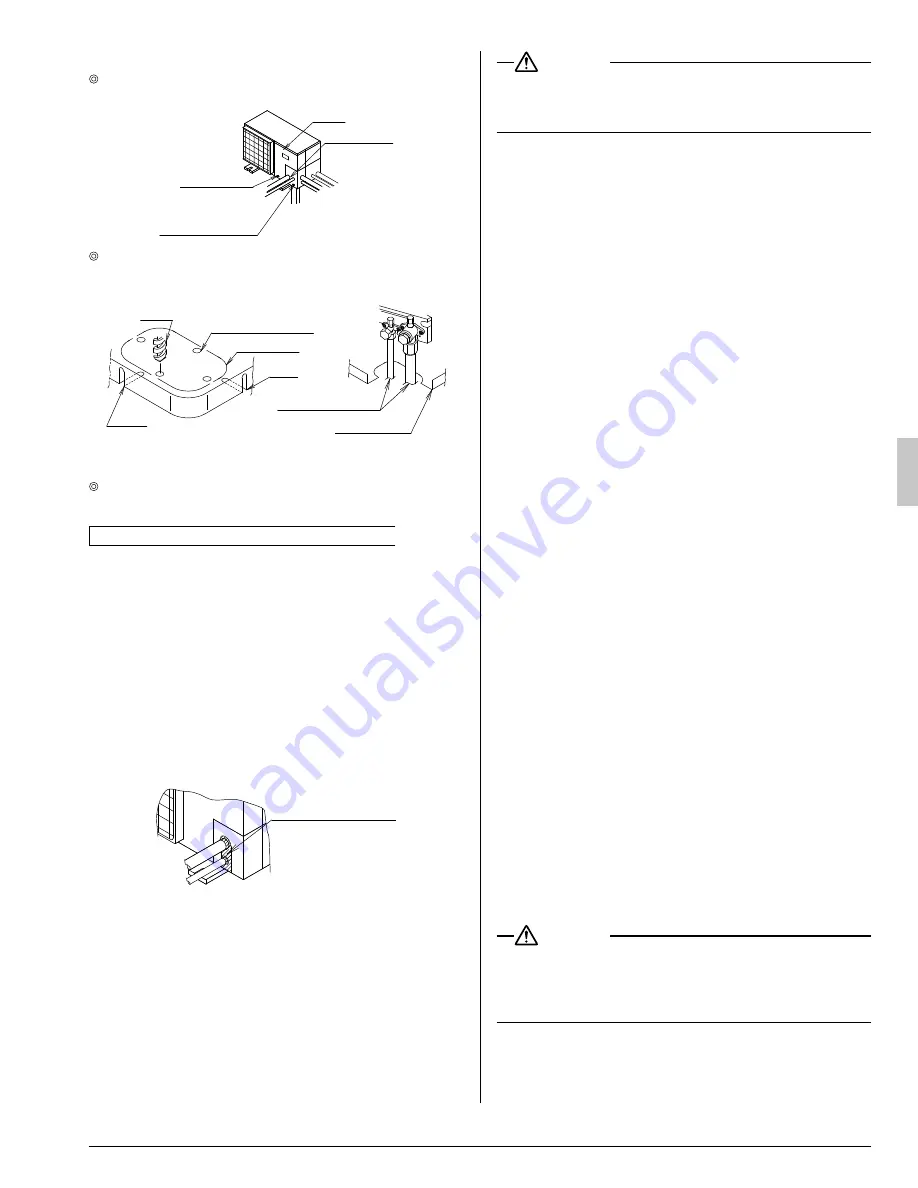
  The fi eld piping can be connected in three directions.

Piping cover

Screw for 
front panel

Screw for piping 
cover (front)

Front 
panel

Lateral 
direction

Front direction

Downward 
direction

  When connecting the pipings downward, remove the knock-

out by making four holes in the middle on the each side of 
the knockout with a drill.

Field pipings

Bottom frame

Knockout

Drill

Slit

Middle on the side

Slit

Then cut out the corner of the bottom frame along the slits (in 
two positions) by using a hacksaw.

  After removing the parts, it is recommended to apply repair 

paint on the edges, to prevent rusting.

Cautions on connecting the connection piping

When it is expected that water condensed in the stop valve 

• 

will reach the indoor unit through the gap between the heat 
insulating material and the piping (for example, when the 
outdoor unit is installed in a higher position than the indoor 
unit), take proper action such as caulking the connection 
area.

[Measures to prevent invasion of small creatures and litter]

Block all gaps in the piping penetration areas with putty or 

• 

heat insulating material (arranged in the local fi eld) as 
shown in the fi gure below.
(If small creatures, such as insects, or litter, enters the 
outdoor unit, a short-circuit may be caused inside the elec-
tric parts box.)

Putty or heat 
insulating material 
(arranged in local field)

Heat insulation of piping

6-5 

Make sure to insulate the fi eld pipings (on both the liquid line 

• 

and gas line) and refrigerant branching kit.
(If they are not insulated, water leakage may be caused.)

(The maximum temperature of the piping on the gas line is 
about 248 °F during heating operation.  Use an insulation 
suffi ciently resistant to this temperature.)

Reinforce the refrigerant piping according to the installation 

• 

environment. If it is not reinforced, condensate may form on 
the surface of the insulation.

 WARNING

Make sure to insulate the fi eld piping up to the piping con-

• 

nection area inside the unit.  If the piping is exposed, dew 
condensation and burn by contact may be caused.

Airtight test and vacuum drying

6-6 

The unit has been checked for leaks by the manufacturer.
Confi rm that the valves are fi rmly closed before airtight test or 
vacuumdrying.
To prevent entry of any impurities and insure suffi cient pres-
sure resistance, always use the special tools dedicated for 
R410A.

Perform the following inspections securely after the 
piping work.

Airtight test

• 

 - Make sure to use nitrogen gas. (For the 

service port position, refer to the fi gure in “

Stop valve 

operation method

”.)

[Procedure]  Pressurize the air conditioner from the liquid 
pipe and gas pipe up to 450 psi (Make sure not to exceed 
450 psi).  When the pressure does not drop for 24 hours, the 
piping work shall be accepted.  
If the pressure drops, check for leakage positions. (Confi rm 
that there is no leakage, then release nitrogen.)

Vacuum drying

• 

 - Use a vacuum pump which can evacuate 

up to –14.6 psi or less.
[Procedure]  Operate the vacuum pump for evacuation for 
2 hours or more using both liquid pipe and gas pipe until the 
vacuum pressure reaches –14.6 psi or less.  Leave the air 
conditioner at –14.6 psi or less for 1 hour or more, and 
confi rm that the vacuum pressure indicated by the vacuum 
gage does not increase.
(If the vacuum pressure increases, the system may contain 
moisture or have leakage.)

If there is a possibility of moisture remaining in the piping


(for example, when there is a possibility of dew condensation 
inside the piping because the piping work was performed in 
the rainy season or over a long period of time, or when rainwa-
ter may have entered the piping during the work)
Perform evacuation described above for 2 hours (vacuum 
drying), pressurize the air conditioner up to 7 psi (vacuum 
break) with nitrogen gas, then evacuate the air conditioner 
using the vacuum pump for 1 hour to achieve –14.6 psi or less 
(vacuum drying).
(If the vacuum pressure does not reach –14.6 psi or less even 
after evacuation for 2 hours or more, repeat vacuum break and 
vacuum drying.) Leave the air conditioner in the vacuum status 
for 1 hour or more, and confi rm that the vacuum pressuree 
indicated by the vacuum gauge does not increase.

Additional refrigerant charge

6-7 

 WARNING

To avoid injury always use protective gloves and eye protec-

• 

tion when charging refrigerant.
To avoid injury do not charge with unsuitable substances. 

• 

Use only the appropriate refrigerant.

01_EN_3PA60114-14U.indd   10

01_EN_3PA60114-14U.indd   10

2/24/2009   5:23:07 PM

2/24/2009   5:23:07 PM

Summary of Contents for SkyAir RZQ18PVJU

Page 1: ... This manual should be left with the equipment owner Lire soigneusement ces instructions avant l installation Conserver ce manuel à portée de main pour référence ultérieure Ce manuel doit être donné au propriétaire de l équipement Lea cuidadosamente estas instrucciones antes de instalar Guarde este manual en un lugar a mano para leer en caso de tener alguna duda Este manual debe permanecer con el ...

Page 2: ...act with fire such as from a fan heater stove or cooking device Exposure to this gas could cause severe injury or death After completing the installation work check that the refrigerant gas does not leak Refrigerant gas may produce toxic gas if it comes in contact with fire such as from a fan heater stove or cooking device Exposure to this gas could cause severe injury or death Safely dispose of t...

Page 3: ... the refrigerant pipes Do not turn off the power immediately after stopping operation Always wait at least five minutes before turning off the power Otherwise water leakage and trouble may occur Do not use a charging cylinder Using a charging cylinder may cause the refrigerant to deteriorate The refrigerant R410A requires strict cautions for keep ing the system clean dry and tight A Clean and dry ...

Page 4: ...D a 0 5 59 115 41 50 50 43 70 95 81 50 23 77 60 67 82 57 A Outdoor temperature FDB B Indoor temperature FWB C Outdoor temperature FWB D Indoor temperature FDB Range for continuous operation Range for pull down operation Range for warming up operation Range for operation Technical specifications 2 2 a and b in the table indicate the operating condition shown in the figure bottom left Model RZQ18PVJ...

Page 5: ...e the air flow rate of the outdoor unit is reduced the outlet air is sucked again short circuit and the following effect may be caused The capacity is deteriorated The adhered frost increases during heating operation The operation is stopped by pressure rise If excessive strong wind continuously blows from the air outlet side of the outdoor unit the fan may rotate in the reverse direction at high ...

Page 6: ...or unit is installed individually 1 When an obstruction is present only on the air inlet side 4 or more When an obstruction is present on the both sides 4 or more 4 or more 4 or more When two or more outdoor units are installed side 2 by side When an obstruction is present on the both sides 40 or more 12 or more 8 or more When an obstruction is present also in the upward area When one outdoor unit...

Page 7: ...ts are installed side 2 by side 12 or more H L 40 or more L H When an obstruction is present also in the upward area When one outdoor unit is installed individually 1 L A 20 or less 40 or more 10 or more H The dimensional relationship between H L and A is as shown in the table below L A L H 0 L 1 2H 30 1 2H L H 40 H L Install the frame to achieve L H NOTE Close the area under the frame so that the...

Page 8: ... L A L H 0 L 1 2H 4 1 2H L H 8 H L Install the frame to achieve L H NOTE Close the area under the frame so that the outlet air does not bypass there When only two outdoor units are installed side by 2 side 60 or more 20 or less H L A 40 or more The dimensional relationship between H L and A is as shown in the table below L A L H 0 L 1 2H 10 1 2H L H 12 H L Install the frame to achieve L H NOTE Clo...

Page 9: ...oundation bolts should be protruded by 15 16 in Refer to figure 13 16 Resin washer Drain treatment In a location where drain from the outdoor unit may cause troubles for example where drainage may splash on gen eral passersby perform the drain piping work using the drain plug optional For drain treatment space of at least 4 in is required under the bottom frame of the outdoor unit In the drain pip...

Page 10: ...film inside the pipes adversely affecting valves and compressor in the refrigerating system and preventing normal operation DANGER Use of oxygen could cause an explosion resulting in severe injury or death Only use nitrogen gas Refrigerant gas may produce toxic gas if it comes in contact with fire such as from a fan heater stove or cooking device Exposure to this gas could cause severe injury or d...

Page 11: ...g 6 6 The unit has been checked for leaks by the manufacturer Confirm that the valves are firmly closed before airtight test or vacuumdrying To prevent entry of any impurities and insure sufficient pres sure resistance always use the special tools dedicated for R410A Perform the following inspections securely after the piping work Airtight test Make sure to use nitrogen gas For the service port po...

Page 12: ...ls you exclusively use on R410A installations to withstand the pressure and to prevent foreign materials from mixing into the system Procedures for charging additional refrigerant Nitrogen Dotted lines represent field piping Cylinder Stop valve service port Vacuum pump Weighing scale Charge hose R410A Pressure reducing valve Outdoor unit Indoor units Liquid line Gas line Siphon system Valve A See ...

Page 13: ...ec tion procedure CAUTION To electrician Do not operate the air conditioner until the refrigerant piping work is completed Operating the air conditioner before the refrigerant piping work is completed may damage the compressor Install an earth leakage circuit interrupter The inverter is provided in the air conditioner In order to prevent malfunction of the earth leakage circuit interrupter itself ...

Page 14: ...re it as described in 7 3 Power supply wiring connection procedure Fix the wiring between the units in accordance with 7 4 Transmission wiring connection procedure Secure the wirings with the clamps accessory so that do not touch the piping Make sure the wirings will not be pinched by the front panel and close the panel firmly Route the conduit along the unit by using a elbow socket and so on to p...

Page 15: ...e table below for tightening torque for the terminal screws Tightening torque ft lbf M5 Power supply and ground terminal block 1 76 2 15 M4 Shielded ground 0 87 1 06 M3 5 Transmission wiring terminal block 0 58 0 72 Transmission wiring connection procedure 7 4 If an excessive force is applied while connecting a cable to the terminal block on the PC board the PC board may be damaged IN D OUT D F1F2...

Page 16: ...he power to the crankcase heater 2 Open the outer panel of the outdoor unit Check the LED on the PC board A1P and A2P in the outdoor unit to see if the data transmission is performed normally One outdoor unit installed H1P H5P H4P H6P H7P H2P H3P HAP Blinking ON OFF LED display LED display Default status before delivery A1P A2P SERVICE MONITOR MODE IND SLAVE MASTER TEST HWL C H SELE CTOR L N O P D...

Page 17: ...ration button since it was first installed a malfunc tion code U3 is displayed In this case perform the check operation by referring to 9 1 Power on and check operation When a malfunction code is displayed in the remote controller Check a malfunction code in the remote controller connected to the indoor unit Malfunction code Cause Solution E3 The stop valves in the outdoor unit remain closed Open ...

Page 18: ...in to which it could leak The unit of measurement of the concentration is lb ft the weight in lb of the refrigerant gas in 1ft volume of the occu pied space Compliance to the local applicable regulations and standards for the maximum allowable concentration level is required Direction of the refrigerant flow Room where refrigerant leak has occurred outflow of all the refrigerant from the system Pa...

Page 19: ...3PA60114 14U EM08A096 0902 HT ...

Reviews: