


3
Note
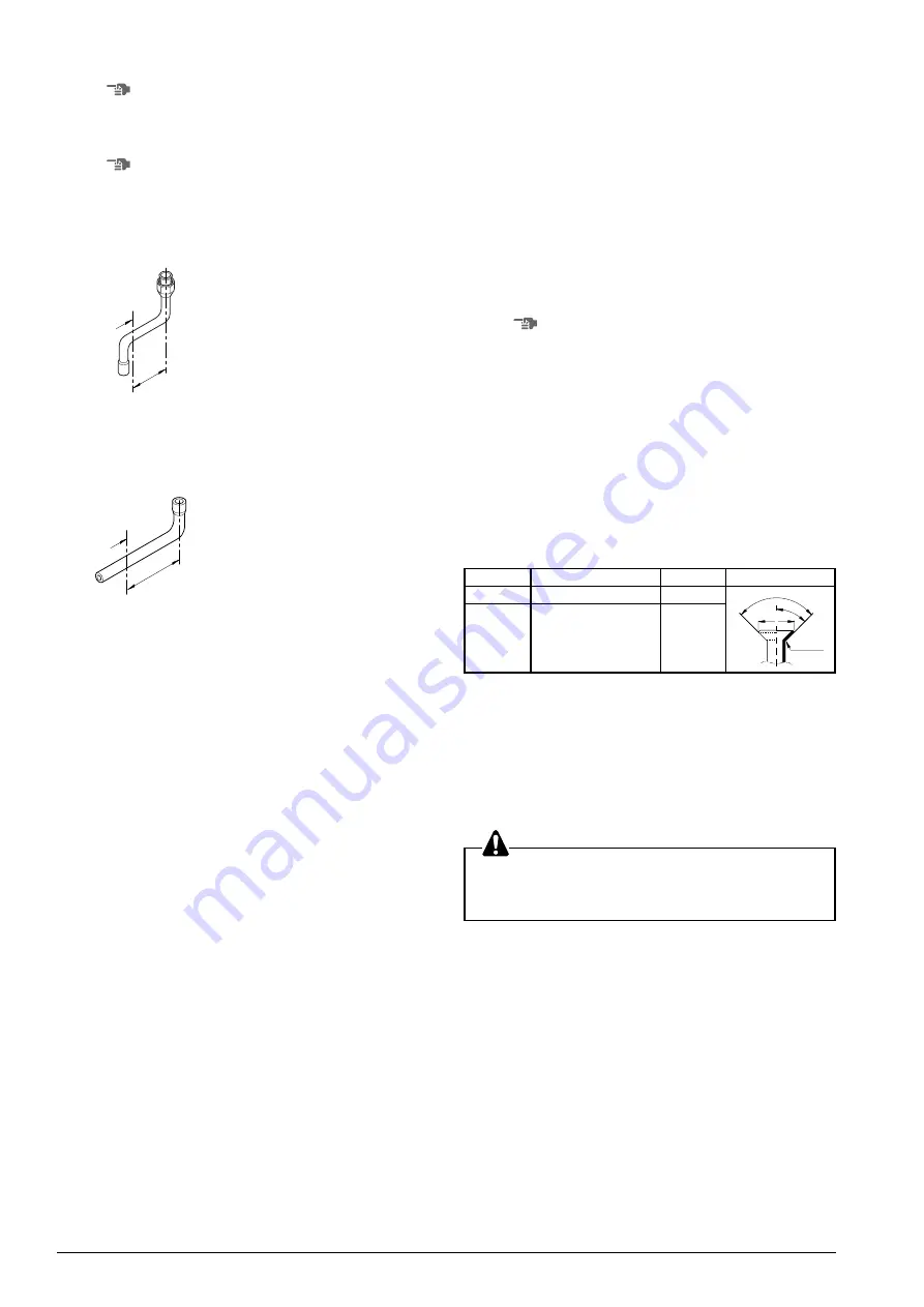
bottom connection
•
Liquid side
Bend the liquid side accessory pipe and connect it to the stop
valve. Take care not to allow it to touch the gas side pipe.
±
75mm
A
A = bending position
•
Gas side
Cut the gas side accessory pipe and make connection using
an elbow (field supply).
±
167mm
A
A = cutting position
2. Make sure to perform the piping installation within the range of
the maximum allowable pipe length, allowable level difference
and allowable length after branching.
In case of simultaneous operation system.
• Upward and downward piping should be performed at the
main piping line.
• Use branch piping kit (optional) for branching of refrigerant
pipes. When using this, follow the following precautions.
(For details, refer to the manual attached to branch piping kit.)
a. Install the branch pipes horizontally (Maximum inclination:
20 degrees or less).
b. Length of branch pipe to the unit should be as short as
possible. (Maximum length: 20 meters or less).
c. Try to keep lengths of both branch pipes to the indoor unit
equal. (Maximum allowable length difference: 10 meters
or less).
3. For installation of the refrigerant branching kit, refer to the
installation manual delivered with the kit.
S
ELECTION
OF
PIPING
MATERIAL
1. Use the following material specification for refrigerant piping:
• Construction material: Phosphoric acid deoxidized
seamless copper for refrigerant.
• Size: Refer to chapter “Refrigerant pipe size and allowable
pipe length”.
• The wall thickness of the refrigerant piping should comply with
relevant local and national regulations. For R22 the allowable
pressure is 2.8 MPa.
H
OW
TO
OPEN
STOP
VALVES
(R
EFER
TO
FIGURE
2)
To open
1. Remove the cap (1) and turn the shaft (2) counter-clockwise
with hexagon socket screw keys (JIS B 4648 nominal size 6 mm
and 10 mm).
2. Turn it all the way until the shaft stops.
3. Tighten the cap firmly.
To close
1. Remove the cap and turn the shaft clockwise.
2. Tighten the shaft firmly until it reaches the sealed area (4) of the
body.
3. Tighten the cap firmly.
Note
- For tightening torques and dimensions of the flares, refer to the
table in the chapter “Flare shape and flarenut tightening torque”.
- Be sure to use both, a spanner and a torque wrench, when
connecting or disconnecting pipes to or from the unit.
- When connecting a flare nut, apply refrigerant oil on the flare
area (both internal and external face), and screw it with your
hand a few times first.
- Use a charging hose with push rod when using the service
port (5).
- Check for refrigerant gas leakage after tightening the cap.
- Make sure to keep stop valve open during operation.
Flare shape and flarenut tightening torque
L
EAK
TEST
AND
VACUUM
DRYING
The units were checked for leaks by the manufacturer.
Confirm that the valves are firmly closed before pressure test or
vacuuming.
After connection of the piping, a leak test must be performed and
the air in the refrigerant piping must be evacuated to a value of
4 mbar absolute by means of a vacuum pump.
Do not purge the air with refrigerants. Use a vacuum pump to
vacuum the installation. No additional refrigerant is provided for
air purging.
1. Perform air evacuation of the piping and a vacuum test.
(There may be no pressure increase for 1 minute.)
2. Break the vacuum with a minimum of 2 bar of nitrogen (N2).
3. Check the connections for leakage. Apply soapsuds to the
connections and inspect carefully. After checking, wipe them off
completely.
4. By way of a final air tight test, check if there is no decrease of
pressure after having left the installation under a pressure of
28 bar during 24 hours.
5. Release the nitrogen.
6. Try to reach perfect vacuum (= gauge reading - atmospheric
pressure of 1013 mbar).
7. Open the valves of the outdoor unit. Let refrigerant flow into
indoor units for equalization through pipes.
R = 0.4~0.8
45
° ±
2
90
°±
4
A
Pipe size
Tightening torque (Ncm)
Ø15.9
6180 ~ 7540
18.6 ~ 19.0
15.4 ~ 15.8
4950 ~ 6030
Ø12.7
A (mm)
Flare shape
Note
front connection
Make sure to close the piping intake hole again after installation
work.


