


6
■
English
3.
Flaring the pipe end
WARNING
•
Do not apply mineral oil to the flare.
• Prevent mineral oil from getting into the system as this would reduce the service life of the units.
• Never use piping which has been used for previous installations. Only use parts which are delivered with this unit.
• Never install a dryer to this R32 unit in order to guarantee its service life.
• The drying material may dissolve and damage the system.
•
Improper flaring may result in refrigerant gas leakage.
CAUTION
• Do not reuse joints which have been used once already.
1) Cut the pipe end with a pipe cutter.
2)
Remove burrs with the cut surface facing
downward, so that the filings do not enter the
pipe.
3) Put the flare nut on the pipe.
4)
Flare the pipe.
5) Check that the flaring has been done correctly.
Cut exactly at
right angles.
Remove
burrs.
The flare’s inner
surface must be
flaw-free.
The pipe end must
be evenly flared in a
perfect circle.
Make sure that the
flare nut is fitted.
When flaring, do
not over-tighten and
crack.
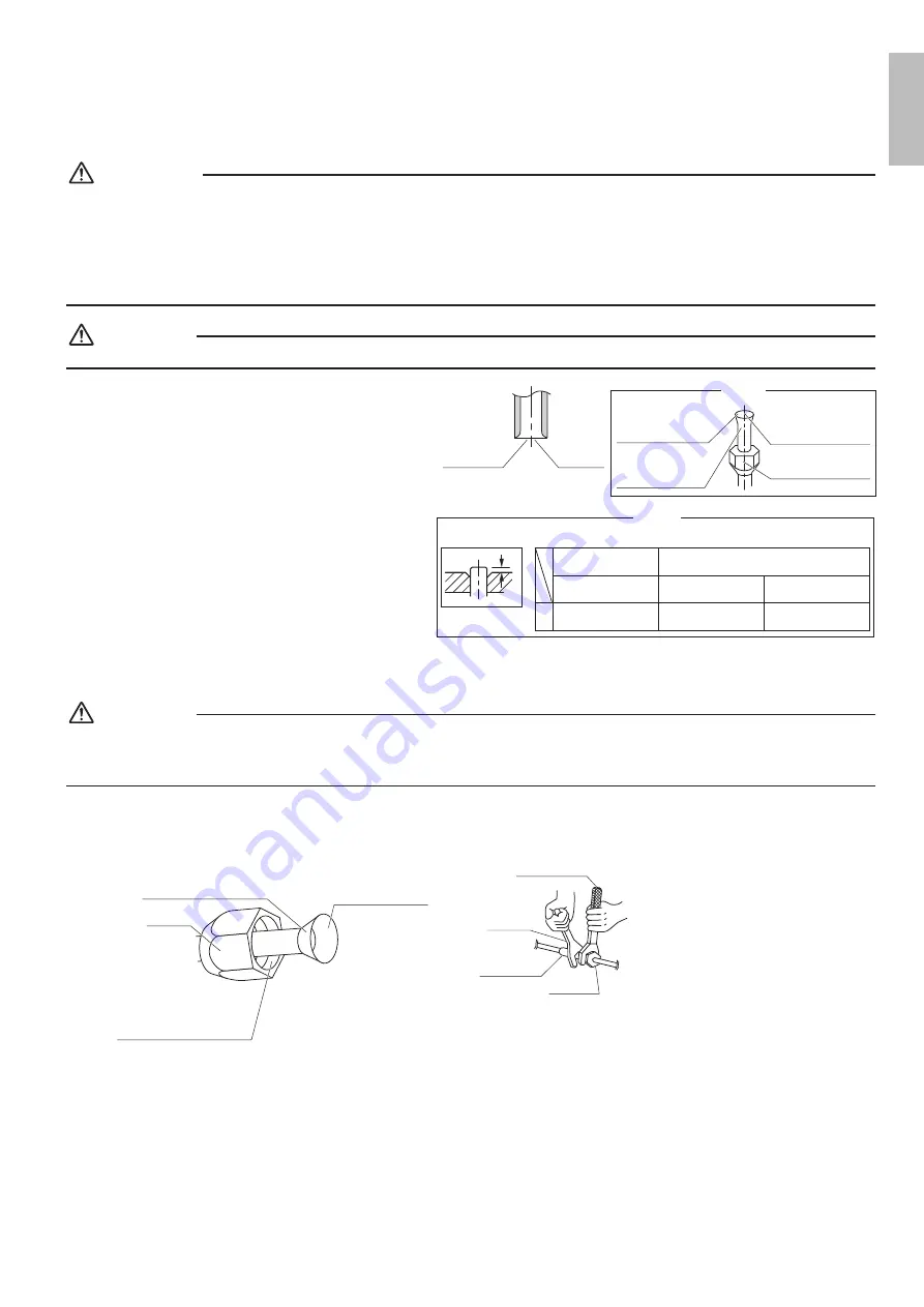
Check
Set exactly at the position shown below.
A
Die
Flare tool for
R32 or R410A
Conventional flare tool
Clutch-type
Clutch-type
(Rigid-type)
Wing-nut type
(Imperial-type)
A
0-0.020 inch
(0-0.5mm)
0.039-0.059 inch
(1.0-1.5mm)
0.059-0.079 inch
(1.5-2.0mm)
Flaring
4.
Refrigerant piping
CAUTION
•
Use the flare nut fixed to the main unit. (This is to prevent the flare nut from cracking as a result of deterioration over time.)
•
To prevent gas leakage, apply refrigeration oil only to the inner surface of the flare. (Use refrigeration oil for R32 or R410A.)
•
Use a torque wrench when tightening the flare nuts to prevent damage to the flare nuts and gas leakage.
•
Align the centers of both flares and tighten the flare nuts 3 or 4 turns by hand, then tighten them fully with a spanner and a
torque wrench.
Apply oil
Do not apply refrigeration
oil to the outer surface.
Do not apply refrigeration
oil to the flare nut to
avoid tightening with
excessive torque.
Apply refrigeration
oil only to the inner
surface of the flare.
Flare nut
Tighten
Torque wrench
Spanner
Piping union
Flare nut
English
01_EN_3P628775-3.indd 6
2021/02/09 13:40:06


