background image

English

12

Precautions when connecting pipes

• See the following table for flare part machining dimensions.
• When connecting the flare nuts, apply refrigerant oil to the inside of 

the flares and turn them three or four times at first.
(Use ester oil or ether oil.)

• See the following table for tightening torque.

(Applying too much torque may cause the flares to crack.)

• After all the piping has been connected, check the gas leak with 

nitrogen.

Not recommendable but in case of emergency

You must use a torque wrench but if you are obliged to install the unit 
without a torque wrench, you may follow the installation method men-
tioned below.

After the work is finished, make sure to check that there is no gas 
leak.

When you keep on tightening the flare nut with a spanner, there is a 
point where the tightening torque suddenly increases. From that posi-
tion, further tighten the flare nut the angle shown below:

(Unit: in.)

9-4 Connecting the refrigerant piping

Connect piping to outside unit by using accessory pipes

(Refer to figure 20)

1.

Gas side piping

2.

(field supply)

3.

Gas side accessory pipe (for suction gas (1))

4.

Liquid side pipe (field supply)

5.

Flare nut (Included in the unit)

6.

Accessory pipes (for discharge gas and suction gas (2)) 
is not used.

7.

Piping on discharge gas side (field supply)

8.

Piping on suction gas side (field supply)

9.

Cut off the hatched area and use it as a cover for the drilled.

10.

Hatched area

11.

Accessory pipe (for discharge gas)

12.

Accessory pipe (for suction gas)

13.

Guideline for pipe machining

14.

Accessory pipe (for suction gas (2))

15.

Brazing

16.

Accessory pipe (for suction gas (1))

17.

Before fitting to the product, apply brazing.

NOTE

Be sure to use the attached pipe when carrying out piping work in 
the field.

Be sure that the local piping does not touch other pipes, the bottom 
panel or side panel. Especially for the bottom and side connection, be 
sure to protect the local piping with the provided insulation, to prevent 
it from coming into contact with the casing.

Precautions for installation of units

NOTE

The outside unit multi connection piping kit that is sold separately as 
an option (BHFP2 84U, BHFP2 84U) is neces-
sary for the multi installation of outside units.

• See the installation manual attached to the kit with attention to instal-

lation restrictions described in “connecting the refrigerant piping” 
when installing.

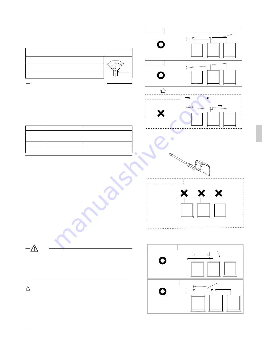
Cautions for installation of multiple outdoor units

1.

The piping between the outdoor units must be routed level or slightly
upward to avoid the risk of oil detention to the piping side.

2.

The gas piping (both discharge and suction gas pipings in case of 
the heat recovery system) after branched, install without fail a trap of 
8 in. or more using the piping included in the piping kit for connecting 
the outside unit. Otherwise, the refrigerant may stay within the pip-
ing, causing any damage to the outside unit.

3.

If the piping length between the outside unit connecting pipe kit or 
between the outside units exceeds 80 in., create a rise of  8 in. or 
more in the gas line within a length of 80 in. from the kit.

pipe size

(in.)

tightening torque

(ft. · lbf)

A

(in.)

flare shape

φ

 3/8”

24.1 - 29.4

0.504 - 0.520

φ

 1/2”

36.5 - 44.5

0.638 - 0.654

φ

 5/8”

45.6 - 55.6

0.760 - 0.776

Pipe size

Further tightening angle

Recommended arm length of tool

φ

 3/8”

60 to 90 degrees

Approx. 7-7/8

φ

 1/2”

30 to 60 degrees

Approx. 9-13/16

φ

 5/8”

30 to 60 degrees

Approx. 11-13/16

φ

 3/4”

20 to 35 degrees

Approx. 17-3/4

R=0.016~0.031

45˚±2

90˚±2

A

Pattern 1

Pattern 2

Prohibited pattern

to indoor
unit

to indoor 
unit

to indoor 
unit

Downward 
inclination

Downward 
inclination

Change to pattern 1 or pattern 2

Oil remains in piping

Piping between outside units

8 in. or more

No trap has been installed in the gas piping.

Oil may remain in the farthest outside unit.

Change to pattern 1 or pattern 2

to indoor unit

Prohibited pattern

to indoor 
unit

to indoor 
unit

If 80 in. or less

If 80 in. or more

80 in. or less

80 in. or less

Rising height: 
8 in. or more

Piping between outside unit

Summary of Contents for RWEYQ72PTJU

Page 1: ...for future reference This manual should be left with the equipment owner Lire soigneusement ces instructions avant I installation Concerver ce manuel port e de main pour r f rence ult rieure Ce manuel...

Page 2: ...6 13 16 3 15 16 9 13 16 21 5 8 30 11 16 9 9 8 10 8 9 7 7 6 6 6 9 7 8 5 8 15 3 8 4 3 1 2 11 13 16 39 3 8 35 7 16 19 11 16 1 2 3 4 4 10 5 6 5 4 9 6 7 7 10 8 1 2 3 4 9 Heat recovery system Heat pump syst...

Page 3: ...figure 13 figure 12 figure 11 A B C A B C F1 F1 F2 F2 Q1 Q2 F1 F2 F1 F2 F1 F2 F1 F2 F1 F2 F1 F2 F1 F2 F1 F2 F1 F2 4 5 6 1 2 7 C H SELECTOR TO IN D UNIT TO OUT D UNIT TO MULTI UNIT 3 A B C F1 F1 F2 F2...

Page 4: ...very system 1 2 3 4 5 6 7 8 9 10 11 5 4 12 14 15 16 17 13 figure 16 A B C A B C 1 DS1 1 2 3 4 OFF ON O U T I N TO IN D UNIT F1 F2 A1P A1P DS1 1 2 3 4 OFF ON O U T I N F1 F2 P1 P2 P1 P2 1 1 2 6 3 3 4 5...

Page 5: ...4 5 6 Heat pump system Heat recovery system 4 5 3 2 1 figure 24 1 11 1 2 2 4 3 4 3 5 5 R410A R410A 9 7 7 8 13 9 6 6 16 10 10 10 10 17 12 12 14 15 15 18 18 Heat pump system Heat recovery system 1 2 3...

Page 6: ...sult in equipment or property damage accidents only DANGER Refrigerant gas is heavier than air and replaces oxygen A massive leak can lead to oxygen depletion especially in base ments and an asphyxiat...

Page 7: ...on tribute to the greenhouse effect if it is released Therefore take proper measures to check for the tightness of the refrig erant piping installation Read the chapter Refrigerant Pip ing and follow...

Page 8: ...itches off automatically in order to protect the unit from freezing Hold ambient temperature at 35 95 F Heat release from the unit 0 64 kW hour Model 72 84 It is therefore recommended to always ventil...

Page 9: ...emale Thread 1 2FPS 2 female Thread General RWEYQ216PTJU RWEYQ252PTJU Nominal cooling capacity 2 MBh 216 252 Nominal cooling capacity 3 MBh 243 283 5 Nominal input cooling heating 4 kW 12 60 12 00 16...

Page 10: ...ower without fail Open type tower cannot be used 4 Strainer Install the strainer accessory without fail at the inlet of water pip ing If sands wastes rust particles etc are mixed in the water cir cula...

Page 11: ...manner 7 1 When designing the equipment 1 Install the strainer accessory at the water inlet side adjacent to the outside unit in order to prevent any foreign materials such as dust sand etc from ente...

Page 12: ...within the standard 2 Clean the strainer 3 Make sure that the flow rate is correct 4 Make sure that the operational conditions pressure flow rate outlet temperature etc are normal 2 Because the plate...

Page 13: ...fect but also may cause the capacitor to overheat due to high frequency waves Therefore never install a phase advancing capacitor Keep power imbalance within 2 of the supply rating 1 Large imbalance w...

Page 14: ...electromagnetic switch for the water pump to each outside unit Select without fail an auxiliary a contact able to switch min imum load of DC15V 1mA When connecting for each outside unit Connect to the...

Page 15: ...erminals for connections to the power terminal block When none is available follow the instructions below Do not connect wiring of different thicknesses to the power termi nal block Slack in the power...

Page 16: ...s always required When installing the piping follow the instructions in the installation manual that comes with the kit Restriction for the installation of the outside unit multi connection piping kit...

Page 17: ...cal piping with the provided insulation to prevent it from coming into contact with the casing Precautions for installation of units NOTE The outside unit multi connection piping kit that is sold sepa...

Page 18: ...c d e f r s t g h j k l m n o p i 23 3 lbs Total length ft of liquid piping size at 7 8 0 235 lbs ft Total length ft of liquid piping size at 3 8 Total length ft of liquid piping size at 1 4 Total len...

Page 19: ...etc this must be prevented by caulking the connections etc WARNING Be sure to insulate connection piping as touching them can cause burns 9 8 Checking of device and installation conditions Be sure to...

Page 20: ...refrigerant 9 10 Stop valve operation procedure CAUTION Do not open the stop valve until 1 6 of 9 8 Checking of device and installation conditions are completed If the stop valve is left open without...

Page 21: ...onfiguration on the main unit Any settings made on a sub unit will be ignored After this close the electrical compo nents box lid Always perform configuration after turning ON the power To learn the s...

Page 22: ...rding to local regulations or standards The following standards may be applicable if local regulations are not available The VRV System like other air conditioning systems uses R410A as refrigerant R4...

Page 23: ...e open ings above and below the door which are each equivalent in size to 0 15 or more of the floor area 3 Calculating the refrigerant density using the results of the calcula tions in steps 1 and 2 a...

Page 24: ...1645 Wallace Drive Suite 110 Carrollton TX 75006 info daikinac com www daikinac com 3P153897 12P EM09A022 0910 FS...

Reviews: