


RR+RQ71+10 RR+RQ7 RR+RQ71~12
RR+RQ71B2W1B
Split System air conditioners
4PW23689-1C
Installation manual
8
E
VACUATING
■
Do not purge the air with refrigerants. Use a vacuum pump to
vacuum the installation. No additional refrigerant is provided for
air purging.
■
Pipes inside the units were checked for leaks by the
manufacturer. The refrigerant pipes fit on site are to be checked
for leaks by the installer.
■
Confirm that the valves are firmly closed before leak test or
vacuuming.
Set up for vacuuming and leak test:
see
Procedure for leak test
Leak test must satisfy EN378-2.
C
HARGING
REFRIGERANT
Important information regarding the refrigerant used
This product contains fluorinated greenhouse gases covered by the
Kyoto Protocol. Do not vent gases into the atmosphere.
Refrigerant type:
R410A
GWP
(1)
value:
1975
(1)
GWP = global warming potential
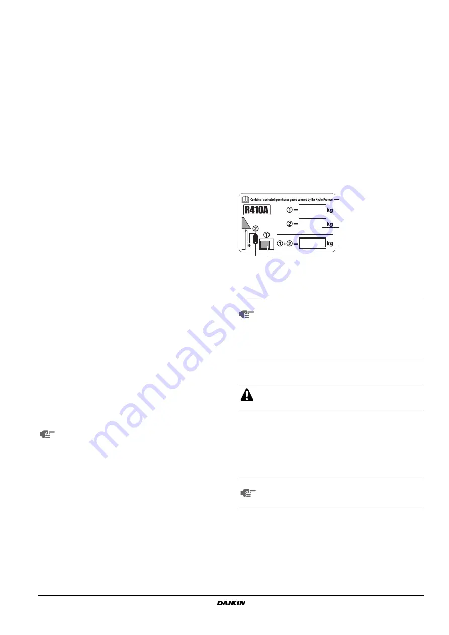
Please fill in with indelible ink,
■
➀
the factory refrigerant charge of the product,
■
➁
the additional refrigerant amount charged in the field and
■
➀
+
➁
the total refrigerant charge
on the fluorinated greenhouse gases label supplied with the product.
The filled out label must be adhered on the inside of the product and
in the proximity of the product charging port (e.g. on the inside of the
service cover).
Precaution for servicing
This unit requires additional charging of refrigerant according to the
length of piping connected at the site. Charge the refrigerant to the
liquid pipe in its liquid state. Since R410A is a mixed refrigerant, its
composition changes if charged in a state of gas and normal system
operation would no longer be assured.
On this model it is not necessary to charge additionaly if the piping
length
≤
30 m.
A
Pair system
B
Simultaneous operation system
1
Pressure gauge
2
Nitrogen
3
Refrigerant
4
Weighing machine
5
Vacuum pump
6
Stop valve
7
Main pipe
8
Branched pipes
9
Pipe branching kit (optional)
1
Evacuate the pipes and check vacuum
(1)
. (No pressure
increase for 1 minute.)
(1) Use a 2-stage vacuum pump with a non return valve which
can evacuate to –100.7 kPa (5 Torr, –755 mm Hg).
Evacuate the system from the liquid and gas pipes by using
a vacuum pump for more than 2 hours and bring the system
to –100.7 kPa. After keeping the system under that condition
for more than one hour, check if the vacuum gauge rises or
not. If it rises, the system may either contain moisture inside
or have leaks.
2
Break the vacuum with a minimum of 2 bar of nitrogen. (Never
pressurize more than 4.15 MPa.)
3
Conduct leak test by applying soap water, etc. to the connecting
part of the pipes.
4
Discharge nitrogen.
5
Evacuate and check vacuum again
.
6
If vacuum gauge does no longer rise, the stop valves can be
opened.
NOTE
Following should be executed if there is a possibility of
moisture remaining in the pipe (if piping work is carried out
during the raining season or over a long period of time,
rainwater may enter the pipe during work).
After evacuating the system for 2 hours, pressurize the
system to 0.05 MPa (vacuum break) with nitrogen gas and
evacuate the system again using the vacuum pump for
1 hour to –100.7 kPa (vacuum drying). If the system
cannot be evacuated to –100.7 kPa within 2 hours, repeat
the operation of vacuum break and vacuum drying. Then
after leaving the system in vacuum for 1 hour, confirm that
the vacuum gauge does not rise.
After air purging with a vacuum pump it may happen that
the refrigerant pressure does not rise, not even if the stop
valve is opened. Reason for this phenomenon is the closed
state of for instance the expansion valve in the outdoor unit
circuit, but this is not a problem for running the unit.
NOTE
National implementation of EU regulation on certain
fluorinated greenhouse gases may require to provide the
appropriate official national language on the unit.
Therefore, an additional multilingual fluorinated greenhouse
gases label is supplied with the unit.
Sticking instructions are illustrated on the backside of that
label.
When performing service on the unit requiring the
refrigerant system to be opened, refrigerant must be
evacuated according to local regulations.
NOTE
On twin/triple application, piping length means sum of
main pipe and branch pipe.
Piping length is the 1 way length, gas or liquid.
3
5
6
2
1
4
1
factory refrigerant charge
of the product:
see unit name plate
2
additional refrigerant
amount charged in the
field
3
total refrigerant charge
4
Contains fluorinated
greenhouse gases
covered by the Kyoto
Protocol
5
outdoor unit
6
refrigerant cylinder and
manifold for charging
Summary of Contents for RQ100B8V3B
Page 17: ...NOTES NOTES...
Page 18: ...4PW23689 1C Copyright Daikin...


