
8
3
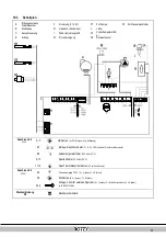
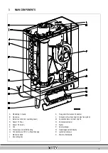
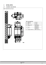
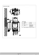
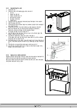
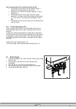
MAIN COMPONENTS
A.
Modulating CH pump
K.
Flue gas/air inlet concentric adapter
B.
Gas valve
L.
Air supply (only when using twin pipe flue system)
C. Burner controller (incl. operating panel)
M. Connection block / terminal strip X4
D. Sensor S1 (flow)
N.
Condensate collector
E.
Sensor S2 (return)
O. Siphon
F.
Fan
P.
Heat exchanger
G. Pressure sensor central heating
Q. Operating panel and display
H. Connection wire 230 V ~ with earthed plug
R.
Ignition/ionization pin
I.
Manual air bleed
S.
Position of data plate
J.
Inspection glass
Summary of Contents for Rotex GW-30 H12
Page 1: ...ROTEX 4P381271 88527701 02 2016 4P381271 88527701 02 2016...
Page 29: ...30...
Page 80: ...30...
Page 132: ...31...
Page 184: ...31...
Page 236: ...31...
Page 287: ...ROTEX Heating Systems GmbH 30...
Page 339: ...30...
Page 392: ...31...