background image

Outdoor Unit Installation (4)

Pump Down Operation

6.

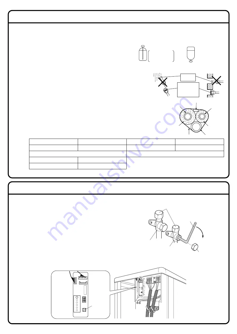
Refilling the refrigerant.

Check the type of refrigerant to be used on the machine nameplate.

Precautions when adding R410A
Fill from the liquid pipe in liquid form.

It is a mixed refrigerant, so adding it in gas form may cause the 
refrigerant composition to change, preventing normal operation.

1) 

Before filling, check whether the cylinder has a siphon attached or not.  
(It should have something like “liquid filling siphon attached” displayed on it.)


Be sure to use the R410A tools to ensure pressure and to prevent foreign objects entering.

7.

Refrigerant piping work.

7-1

Cautions on pipe handling.

1) Protect the open end of the pipe against dust and moisture.
2) All pipe bends should be as gentle as possible. Use a pipe bender for bending.

7-2

Selection of copper and heat insulation materials.

When using commercial copper pipes and fittings, observe the following:
1) Insulation material:  Polyethylene foam 

Heat transfer rate:  0.041 to 0.052W/mK (0.024 to 0.030Btu/fth˚F (0.035 to 0.045kcal/mh˚C))
Refrigerant gas pipe’s surface temperature reaches 230˚F (110˚C) max.
Choose heat insulation materials that will withstand this temperature.

2) Be sure to insulate both the gas and liquid piping and to provide insulation 

dimensions as below.

In order to protect the environment, be sure to pump down when relocating or disposing of the unit.

1) Remove the valve cap from liquid stop valve and gas stop valve.
2) Carry out forced cooling operation.
3) After 5 to 10 minutes, close the liquid stop valve with a 

hexagonal wrench.

4) After 2 to 3 minutes, close the gas stop valve and stop forced 

cooling operation.

Forced cooling operation

1) Press the Forced Operation switch (SW1) to begin forced cooling. Press the Forced Operation switch (SW1) again 

to stop forced cooling.

3)

Use separate thermal insulation pipes for gas and liquid refrigerant pipes.

Gas side

O.D. 5/8 inch (15.9mm)

1-15/16 inch (50mm) or more

Thickness 0.039 inch (1.0mm) (C1220T-O)

Liquid side

O.D. 3/8 inch (9.5mm)


1-3/16 inch (30mm) or more

Thickness 0.031 inch (0.8mm) (C1220T-O)

Gas pipe thermal insulation

I.D. 0.630-0.787 inch (16-20mm)

Thickness 0.393 inch (10mm) Min.

Liquid pipe thermal insulation

I.D. 0.472-0.591 inch (12-15mm)

Minimum bend radius

Wall

If no flare cap is 
available, cover the 
flare mouth with 
tape to keep dirt or 
water out.

Be sure to 
place a cap.

Rain

Gas pipe

Liquid pipe

Gas pipe 
insulation

Liquid pipe 
insulation

Finishing tape

Drain hose

Inter-unit wire

LED-A

SW4

ON

AB

C

D

S102

SW1

S2

Forced 
operation 
switch

Close

valve cap

Hexagonal 
wrench

Service port

Liquid stop valve

Gas stop valve

Filling a cylinder with an 
attached siphon

Stand the cylinder upright 
when filling.

There is a siphon pipe 
inside, so the cylinder 
need not be upside-
down to fill with liquid.

Filling other cylinders

Turn the cylinder 
upside-down when filling.

Summary of Contents for RKS30

Page 1: ... if it comes in contact with fire such as from a fan heater stove or cooking device Exposure to this gas could cause severe injury or death Do not ground units to water pipes telephone wires or lightning rods because incomplete grounding could cause a severe shock hazard resulting in severe injury or death and to gas pipes because a gas leak could result in an explosion which could lead to severe ...

Page 2: ...ecified types of wires for electrical connections between the indoor and outdoor units Follow all state and local electrical codes Firmly clamp the inter unit wire so their terminals receive no external stresses Incomplete connections or clamping may cause terminal overheating fire or equipment damage After connecting all wiring be sure to shape the cables so that they do not put undue stress on t...

Page 3: ... under the unit anything which must be kept away from moisture NOTE Cannot be installed hanging from ceiling or stacked Check the strength and level of the installation ground so that the unit will not cause any operating vibration or noise after installed In accordance with the foundation drawing fix the unit securely by means of the foundation bolts Prepare four sets of 1 2 inch M12 foundation b...

Page 4: ...mm of work space below the ceiling surface 9 7 8 250mm from wall Allow space for piping and electrical servicing Right side plate 13 5 8 345mm Clamping material Insulation tube Bottom frame Tape Also insulate the connection on the outdoor unit Use tape or insulating material on all connections to prevent air from getting in between the copper piping and the insulation tube Be sure to do this if th...

Page 5: ...ps into their matching drain hole Drain socket A into drain hole I and drain caps B into drain hole II and III After insertion turn them about 40 clockwise Be sure not to insert them into wrong drain holes or there causes water leakage View from bottom 3 Connect vinyl hose on the market internal diameter of 1 inch 25mm to drain socket A If the hose is too long and hangs down fix it carefully to pr...

Page 6: ...9 7N m Valve cap tightening torque Service port cap tightening torque 7 9 10 8ft lbf 10 8 14 7N m CAUTION 1 Use the flare nut fixed to the main unit To prevent cracking of the flare nut by aged deterioration 2 To prevent gas leakage apply refrigeration oil only to the inner surface of the flare Use refrigeration oil for R410A 3 Use torque wrenches when tightening the flare nuts to prevent damage t...

Page 7: ...mage the vacuum pump or the unit 1 Connect projection side of charging hose which comes from gauge manifold to gas stop valve s service port 2 Fully open gauge manifold s low pressure valve Lo and completely close its high pressure valve Hi High pressure valve subsequently requires no operation 3 Do vacuum pumping and make sure that the compound pressure gauge reads 29 9inHg 0 1MPa 1 4 Close gauge...

Page 8: ...sure to pump down when relocating or disposing of the unit 1 Remove the valve cap from liquid stop valve and gas stop valve 2 Carry out forced cooling operation 3 After 5 to 10 minutes close the liquid stop valve with a hexagonal wrench 4 After 2 to 3 minutes close the gas stop valve and stop forced cooling operation Forced cooling operation 1 Press the Forced Operation switch SW1 to begin forced ...

Page 9: ...er harmonics This unit uses an inverter which means that it must be used an earth leak detector capable handling harmonics in order to prevent malfunctioning of the earth leak detector itself 4 Use an all pole disconnection type breaker with at least 1 8 inch 3mm between the contact point gaps 5 When carrying out wiring connection take care not to pull at the conduit 6 Do not connect the power wir...

Page 10: ...voidable reasons be sure to observe the following instruction Place the round crimp style terminals on the wires up to the covered part and secure in place Ground terminal installation Use the following method when installing the round crimp style terminal CAUTION 1 Stranded wire Round crimp style terminal 1 2 3 1 2 3 Safety breaker 20A Earth leakage circuit breaker Earth Firmly fix the wires with...

Page 11: ...door temperature rises the operation will start again 1 If the outdoor unit is installed where the heat exchanger of the unit is exposed to direct wind provide a windbreak wall 2 Intermittent noises may be produced by the indoor unit due to the outdoor fan turning on and off when using facility settings 3 Do not place humidifiers or other items which might raise the humidity in rooms where facilit...

Page 12: ...ter it is turned off 1 3 Carry out the test operation in accordance with the operation manual to ensure that all functions and parts are working properly The air conditioner requires a small amount of power in its standby mode If the system is not to be used for some time after installation shut off the circuit breaker to eliminate unnecessary power consumption If the circuit breaker trips to shut...

Page 13: ...3P235796 1F M08B133E ...

Reviews: