background image

40

FOR PROPER CHARGING OF A SYSTEM, SEE EQUIPMENT 

INSTALLATION MANUAL.

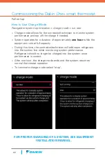
How to Use Charge Mode

Navigate to system optimization > charge mode > run test


»

Charge mode allows for the contractor/technician to monitor system 

performance and top off the charge if needed.


»

System operates for a duration of approximately 

one hour

 while the 

equipment runs at full capacity. 


»

During this time, the contractor/technician will add vapor refrigerant 

into the suction line while monitoring system performance.

Refrigerant should no longer be charged into the system once 

performance is correct.


»

After one hour, the charge mode ends and the system resumes 

normal thermostat operation.


»

To terminate charge mode select ‘stop’. 

Full set-up

Commissioning the Daikin 

One

+ smart thermostat

Summary of Contents for One+

Page 1: ...Daikin One smart thermostat Reference Guide...

Page 2: ...h may result In addition in jurisdictions that require one or more licenses to service the equipment specified in this manual only licensed personnel should servise the equipment Improper installation...

Page 3: ...32 Step 2 Communication 33 Step 3 Equipment Set up 34 How to Configure Humidifier on Modulating and 2 stage Furnaces 35 How to Configure Heat Kit 35 How to Set up Lockout Temperature for Heat Pump 37...

Page 4: ......

Page 5: ...Introduction...

Page 6: ...any menu with a single tap An integrated Wi Fi radio connects to the internet via a home router to the cloud and onto the homeowner mobile application The Daikin cloud will also seamlessly integrate...

Page 7: ...7 Turning the dial changes the temperature set point A number of screen savers are available including this analog clock 1 4 5 2 3 INTRODUCTION...

Page 8: ...to help answer questions during the installation and commissioning Scanning the bar code on the bottom left corner will link you to a website related to the title of the card For further details on th...

Page 9: ...er for communicating HVAC systems Indoor Unit Furnace Coil Air Handler Blower DM97MC DC97MC DM96VC DC96VC DM80VC DC80VC CAPE CHPE DVFEC DVPEC DVPVC DVPTC MBVC Outdoor Unit Air Conditioner DX20VC DX17V...

Page 10: ...y 5 from the floor On an interior wall using the included screws Important Notes You do not need the trim plate to mount the thermostat Screws included are designed to mount in sheetrock or studs Its...

Page 11: ...t to communicating outdoor units Connect 1 2 C and R from the Daikin One to 1 2 C and R at the indoor unit Connect wires 1 and 2 from the indoor unit to 1 and 2 at the outdoor unit Wiring communicatin...

Page 12: ...move the connector to the far left to pair R C G W1 on the 9 pin with 1 2 R C on the indoor PCB Communicating outdoor units supplied with a 7 pin connector only will move the connector to the far lef...

Page 13: ...s with a 4 pin connector supplied will match 1 2 R C on the 4 pin with 1 2 R C on the indoor PCB Communicating outdoor units with a 4 pin connector supplied will match 1 2 on the 4 pin with 1 2 on the...

Page 14: ...14 Wiring Diagram...

Page 15: ...length of wire is 125 ft Communicating OUTDOOR UNIT DX17VSS Compatible Communicating INDOOR UNIT Daikin One Smart Thermostat Communicating FIT System with AHU Plug Play System Only four wires require...

Page 16: ...16 Wiring Diagram...

Page 17: ...d HUM OUT HUM IN must be powered with the desired voltage 24 VAC from the R terminal or 115 VAC from L1 terminal Humidification relay turns ON when there is call for heat and a call for humidification...

Page 18: ...ixing all the wiring issues apply power Check for 24 VAC across R 24 VAC and C 24 VAC common terminals If there are still problems discovering the indoor or outdoor equipment then check for bias readi...

Page 19: ...ts terminal blocks Take Bias readings on CAPE EEV coil if connected by repeating above steps on its terminal blocks The Bias readings should match on all the equipment s terminal blocks If Bias readin...

Page 20: ...20 Wiring Troubleshooting View of the DS1 Switch on the Outdoor Unit PC Boards 1 17 SEER Daikin Fit...

Page 21: ...21 INTRODUCTION 2 18 SEER all tonnage...

Page 22: ...22 Wiring Troubleshooting 3 20 SEER 2 and 3 Ton...

Page 23: ...23 INTRODUCTION 4 20 SEER 4 Ton...

Page 24: ...24 Wiring Troubleshooting 5 20 SEER 5 Ton...

Page 25: ......

Page 26: ......

Page 27: ...System Power Up...

Page 28: ......

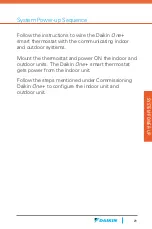
Page 29: ...rt thermostat with the communicating indoor and outdoor systems Mount the thermostat and power ON the indoor and outdoor units The Daikin One smart thermostat gets power from the indoor unit Follow th...

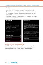
Page 30: ...ust be started with default settings Start up screen is displayed upon powering the thermostat The welcome screen displays basic instructions An explanation of two set up options is displayed on the l...

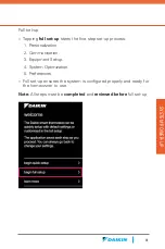
Page 31: ...step set up process 1 Personalization 2 Communication 3 Equipment Set up 4 System Optimization 5 Preferences Full set up ensures the system is configured properly and ready for the homeowner to use N...

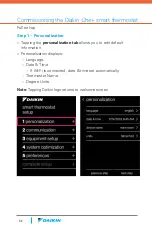
Page 32: ...you to edit default information Personalization displays Language Date Time If Wi Fi is connected date time set automatically Thermostat Name Degree Units Note Tapping Daikin logo returns to welcome...

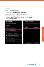
Page 33: ...n Con gures Communication Networks Select home Wi Fi to search for networks With Wi Fi con gured the system can check the software version and update software to the latest version automatically Full...

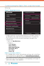
Page 34: ...pdf Menus and sub menus will display or not depending on the type of indoor and outdoor units detected Displays equipment found by searching the communication network or by adding removing equipment...

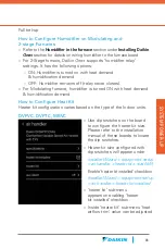
Page 35: ...heat airflow trim value can be adjusted How to Configure Humidifier on Modulating and 2 stage Furnaces Refer to the Humidifier in the furnace section under Installing Daikin One section for details o...

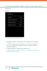
Page 36: ...handler heater kit size kW Select the heater kit size by scrolling available size kW options If required adjust electric heat airflow trim Installer Wizard equipment setup air handler heater kit elec...

Page 37: ...t temperatures Backup heat is requested immediately if the difference between the heat set point and indoor temperature is greater than 4 F Depending on load conditions and system performance the ther...

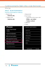
Page 38: ...ization displays System test Inverters only Charge mode Inverters only Optional test Error history Logs alerts with an error code White not critical Yellow critical Calibration Status Full set up Comm...

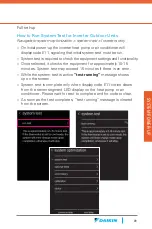
Page 39: ...tionality Once selected it checks the equipment for approximately 10 15 minutes System test may exceed 15 minutes if there is an error While the system test is active test running message shows up on...

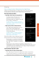
Page 40: ...r a duration of approximately one hour while the equipment runs at full capacity During this time the contractor technician will add vapor refrigerant into the suction line while monitoring system per...

Page 41: ...ate to system optimization calibration temperature calibration To calibrate or make adjustment to the thermostat displayed temperature drag the offset up or down Adjustment can be made 7 F to 7 F in 1...

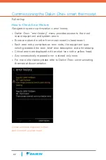
Page 42: ...are stored in order from most recent to least recent Each error entry comprises an error code the equipment type which generated the error brief error description and a timestamp Critical errors are d...

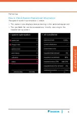
Page 43: ...Information Navigate to system optimization status The status menu displays data pertaining to the selected equipment The scrollable list can be accessed any time by returning to the installer set up...

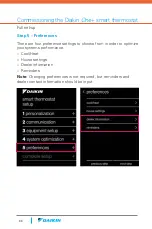
Page 44: ...ptimize your systems performance Cool Heat House settings Dealer information Reminders Note Changing preferences is not required but reminders and dealer contact information should be input Step 5 Pre...

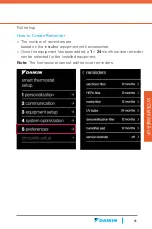
Page 45: ...ased on the installed equipment with accessories Once the equipment has been added a 1 24 month service reminder can be selected for the installed equipment Note The homeowner cannot edit service remi...

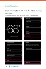
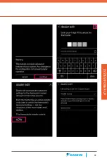
Page 46: ...nced adjustments to the Daikin One will be made here How to return to Dealer Edit mode Full Set up Navigating to dealer edit will allow you to access or revisit the installer set up screen Dealer Navi...

Page 47: ...47 SYSTEM POWER UP...

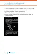
Page 48: ...te to settings comfort target humidity Drag the value left or right to set the target humidity level Top value displays the target humidification level Bottom value displays the target dehumidificatio...

Page 49: ......

Page 50: ......

Page 51: ...References...

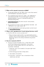
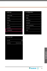
Page 52: ...ning content can be found on www DaikinCity com 2 What to do if equipment isn t found during discovery mode a Find the AHU but not the outdoor unit i Ensure wiring is tight as this may cause dysfuncti...

Page 53: ...53 REFERENCES...

Page 54: ...wner Welcome page https www daikinone com smart_thermostats oneplus welcome Contains information for homeowner for how to use Daikin One Smart Thermostat and how to use the mobile app Professional Con...

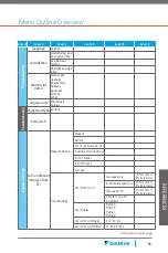
Page 55: ...ipment Setup Air Conditioner model from CT Specifications Model Serial Control Software Version Inverter Software Version of AC Stages of HP Stages Tonnage Cool Settings Cool Airflow Trim Low speed tr...

Page 56: ...speed trim 15 to 15 in 3 increments Intermediate speed trim 15 to 15 in 3 increments High speed trim 15 to 15 in 3 increments 10 to 10 in 2 increments Cool Profiles Profile A Profile B Profile C Prof...

Page 57: ...out heat pump lockout temp 20 F to 65 F in 5 F increments enable aux heat lockout aux heat lockout temp 10 F to 75 F in 5 F increments Furnace model from CT Specifications Model Serial Control Softwar...

Page 58: ...8 10 15 20 25kW Electric Heat Airflow Trim 0 to 10 in 2 steps 10 to 10 in 2 steps Heat Airflow ON Delay Heat Airflow OFF Delay Humidifier Relay Humidifier Enable with Blower None Humidification Mode O...

Page 59: ...nts 10 to 10 in 2 increments Cool Profiles Profile A Profile B Profile C Profile D Cool Airflow ON Delay 5 10 20 30s 1 5 10 20 30s Cool Airflow OFF Delay 30 60 90 120s 0 30 60 90 120s Remove equipment...

Page 60: ...Electronic filter Number of filters 1 2 Remove equipment Do you want to remove this equipment Yes No Zone Board Type EWC Zone Board Zone 1 radio button Additional Zone radio button Remove equipment D...

Page 61: ...ump operation mode current critical error current minor error requested heat demand requested cool demand requested indoor CFM requested indoor fan demand requested dehumidification demand compressor...

Page 62: ...ion demand requested dehumidification demand refrigerant type calculated superheat calculated subcool fan runtime liquid temperature suction temperature pressure sensor Furnace operation mode current...

Page 63: ...midification overcool 0 1 2 or 3 F boost mode on off boost mode outdoor activation temperature Always ON 70 F 75 F 80 F 85 F 90 F 95 F 100 F 105 F house settings quiet mode enable quiet mode check box...

Page 64: ...months dehumidification filter off 1 3 6 or 12 months humidifier pad off 3 6 or 12 months service reminder off 3 6 or 12 months add custom reminder Name enter text 1 24 months dealer information deal...

Page 65: ...an experienced radio TV technician for help REMARQUE Cet quipement a t test et d clar conforme aux limites impos es aux appareils num riques de classe B conform ment la section 15 du r glement de la F...

Page 66: ...er holes in the wall place the trim plate against the wall first Then use the included screws to secure the terminal plate to the wall sandwiching the trim plate if you re using it After connecting th...

Page 67: ...67 Notes...

Page 68: ...68 Notes...

Page 69: ...69 Notes...

Page 70: ...70 Notes...

Page 71: ...t HVAC Heating Ventilation Air Conditioning manufacturers in the world DIL is primarily engaged in developing indoor comfort products and refrigeration systems for residential commercial and industria...

Page 72: ...2019 For more information Sales and Technical Support 1 855 DAIKIN1 www daikincomfort com or daikinac com PM ONE ST 11 19 www daikincity com...

Reviews: