


O-UC12-FEB23-3
Page 4
Service and Maintenance
A preventative maintenance schedule should be set up as
soon as the Unit Cooler is installed. The unit should be
inspected periodically for proper operation and buildup
of dirt.
1.
Inspect and clean the drain pan to ensure there is
no blockage. The drain pan should be cleaned
regularly with warm water and neutral detergent.
2. The cabinet can be cleaned with water and neutral
detergent. DO NOT clean the fans and fins using a water
jet or high-pressure cleaner.
3. The evaporator coil should be checked once a month for
proper defrosting. Many variables affect coil frosting
such as room temperature, type of product being stored,
how often new product is brought in and the length of
time the door to the room remains open. Summer
conditions of high humidity can cause heavier frost loads.
It may be necessary to change the numbers of defrost
cycles seasonally.
4. At least every six months check all fan motors. Tighten
motor mounting screws and fan set screws.
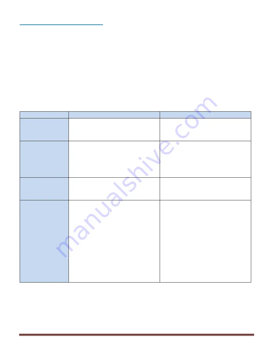
Table 1: Troubleshooting Chart
PROBLEM
POSSIBLE CAUSES
CORRECTIVE ACTION
Excessive buildup of
frost on coil.
•
Defrost time is too short.
•
Extend defrost period on the
temperature controller.
•
Too high humidity in room.
•
Limit access to cold room; do not keep
doors open during stocking.
Accumulation of ice or
water in drain pan.
•
Drain line plugged.
•
Clean drain line. Make sure drain line is
insulated properly.
•
Drainpipe does not have slope angle.
•
Install the drain line with slope.
•
Indoor unit does not install in level at all
directions.
•
Check unit installation and align the unit
level at all directions.
•
Drain line does not have drain trap.
•
Install drain line trap.
Noise
•
· Resonance on the vibrating
mounting parts.
•
Fix the position of vibrating part
correctly.
•
Vibration of fan or fan mounting
misaligned.
•
Fix the position of fan correctly; replace
if defective.
Room temperature too
high (not cold)
•
Incorrect setting on the temperature
controller.
•
Correct the temperature controller
setting.
•
The compressor stopped by alarms
triggered on the controller.
•
Check the type of error, fix the error
and replace the defective parts if any.
•
Incorrect sensor temperature.
•
Check the room temperature sensor
location. Ensure it was not affected by
other sources.
•
Insufficient
refrigerant
flow
to
evaporator.
•
Check for any refrigerant leakage or
choking on expansion valve. Repair the
fault and charge system if necessary.
•
Thick frost built on evaporator coil.
•
Defrost the coil and clean the frost.
•
Too frequent defrosting.
•
Reduce defrost cycle frequency.
•
Incorrect matching of indoor capacity to
outdoor.
•
Review
and
reselect
the
unit
combination.


