21/77
Operation Manual
D
–EOMWC00A07-16_02EN
7.10.1
Cond In/Cond Out condensation control
If the Condensation Control Value Set Point is set to Cond In or Cond Out options, then Tower fan #1..4 control is enabled
for the unit.
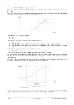
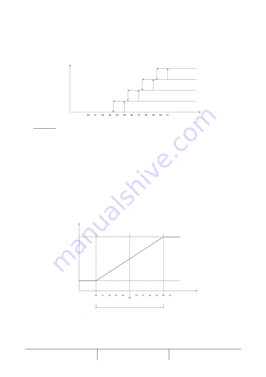
According to Tower fan #1..4 set point and differential default values listed in the Unit Set Points table, the following graph
summarizes the activation and deactivation conditions for Towers fan.
The Tower fan # (# = 1..4) control states are:
•
Off
•
On
The Tower fan # control state is Off when any of the following are true:
•
Unit state is Off
•
Tower fan # state is Off and EWT (Cond In) or LWT (Cond Out) is lower than Tower fan # Set point
•
Tower fan # state is On and EWT (Cond In) or LWT (Cond Out) is lower than Tower fan # Set point
– Tower fan
# Diff.
The Tower fan # control state is On when all of the following are true:
•
The unit state is auto
•
EWT (Cond In) or LWT (Cond Out) is equal or higher than Tower fan # Set point
If the Condensation Control Value Set Point is set to Cond In or Cond Out options and Cond Aout type Set Point is set to
Vfd or Byp Valve options, a 0-10V signal is also enabled for the unit to regulate a modulating condensation device by mean
of a PID controller.
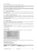
According to Vfd/Byp Valve default values listed in the Unit Set Points table, the following graph is an example of the
modulating signal behavior in case of a control supposed to be purely proportional.
In this case, the analog output varies across the regulation band calculated as Condenser Water Temp Set Point ± 100/kp,
where kp is the control proportional gain, and centered on the Condenser Water Temp Set Point.
Tower
Output
T° Cond
(In/Out
Tower
#1
Tower
#2
Tower
#3
Tower
#4
Analog
output max
value (10 V)
Analog
output min
value (0 V)
T° Cond
(In/Out
Cond In/Out
Temp Set Point
Regulation Band = 100/KP
KP = PID Proportional Gain

