background image

I

nsTallaTIon

www.DaikinApplied.com 25 

IOM 1210-7 • MAGNITUDE

®

 MODEL WMC CHILLERS


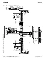
























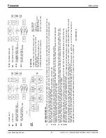
NO

T

ES:



UNI

T

 CO

NT

RO

L

 BO

F

A

CT

O

RY

 A

SSEM

BL

Y

:

J

UM

PERS 

WJ

1

 AND 

WJ

2

 M

UST

 O

NL

Y

 BE 

CO

NNECT

ED 

T

O

 T

ERM

INAL

 BL

O

CK 

33

.



CHI

L

L

ER 

F

A

CT

O

RY

 A

SSEM

BL

Y

:

IF

 O

P

T

IO

N

A

L


GF

P

2

 I

USED 

T

HEN 

REM

O

VE 

J

UM

PER 

WJ

2

O

T

HERW

ISE 

CO

M

PL

ET

CO

NNECT

IO

WJ

2

 T

O

 T

ERM

INAL

 BL

O

CK 

39

.



CHI

L

L

ER 

F

A

CT

O

RY

 A

SSEM

BL

Y

:

CO

NNECT

IO

F

RO

M

 EF

0

 T

O

 7

0

 & 

CF

0

 T

O

 7

0

 REQ

UI

RED 

O

NL

Y

 W

HEN 

F

L

O

W

 SW

IT

CH 

#

3

3

1

8

9

3

9

0

1

 (

IF

M

 EF

ECT

O

R,

 I

NC 

#

 SI

O

5

5

8

IS 

USED.






IF

 O

P

T

IO

N

A

L


GF

P

1

 I

USED 

T

HEN 

REM

O

VE 

J

UM

PER 

WJ

1

O

T

HERW

ISE 

CO

M

PL

ET

CO

NNECT

IO

WJ

1

 T

O

 T

ERM

INAL

 BL

O

CK 

38

.
Summary of Contents for Magnitude

Page 1: ...ntenance Manual Magnitude Magnetic Bearing Centrifugal Chillers Model WMC D Model TMC 125 to 400 Tons 440 to 1400 kW HFC 134a Refrigerant 50 60 Hz IOM 1210 7 Group Chiller Part Number IOM1210 7 Date J...

Page 2: ...Operation 28 Maintenance 63 Appendix 65 2018 Daikin Applied Illustrations and data cover the Daikin Applied product at the time of publication and we reserve the right to make changes in design and co...

Page 3: ...ectrical Code and local codes See Note 4 Condenser pump starting relay CP1 2 installed and wired See Note 3 Miscellaneous Yes No N A Initials Oil cooled water piping complete Units with water cooled o...

Page 4: ......

Page 5: ...sed An electrical charge builds when halo carbon refrigerant travels in a rubber hose A grounding strap must be used between the auxiliary refrigerant tank and the chiller s end sheet earth ground whi...

Page 6: ...terlocks are required thereby simplifying installation and increasing reliability Necessary equipment protection and operating controls are included All Daikin Applied centrifugal chillers must be com...

Page 7: ...Tech II unit controller is to acquire and process data relating to chiller operation issue instructions to various components of the chiller and maintain controlled operation of the chiller As a part...

Page 8: ...unit is equipped with a shipping skid leave the skid in place until the unit is in its final position This will aid in handling the equipment CAUTION Extreme care must be used when rigging the unit t...

Page 9: ...mm Height in mm Shipping Weight lb kg 036D SN E2209 C2009 134 70 3421 43 42 1103 79 02 2007 6367 2888 036D SN E2212 C2012 169 59 4308 43 42 1103 79 02 2007 7477 3392 043D SN E2609 C2209 135 72 3447 4...

Page 10: ...ing weight is based on unit with standard tube configuration Denotes unit with economizer NOTE See certified drawings for additional dimensional data Model Heat Exchanger Length in mm Width in mm Heig...

Page 11: ...field disassembly and reassembly on site Unit ships completely assembled to the jobsite Suction and discharge lines have bolt on flanges Motor cooling line is brazed at mechanical connections see Det...

Page 12: ...r s and vessels receive an inert gas holding charge Unit ships with replacement refrigerant gaskets and O rings stick on wire ties and touch up paint Unit is fully tested at the factory prior to shipm...

Page 13: ...nit length width and height dimensions for WMC models LIQUID LINE IS PAST THE TUBE SHEET ENVELOPE AS SHOWN WHEN DISASSEMBLING VESSELS PRECAUTIONS WILL NEED TO BE TAKEN TO PROTECT PIPING LLTS WMC400 on...

Page 14: ...h Evaporator Assembly Width of Tubesheet ETSH Overall Height Evaporator Assembly Bottom of Foot to Top of Joining Flanges LLTS Height of Parts Extending Beyond Tubesheet TH Overall Height of Parts Ext...

Page 15: ...he spreader bar in Figure 12 is a representation only and may not reflect the appearance of the actual spreader bar needed Compressor Removal and Re Attachment Instructions Follow the steps listed to...

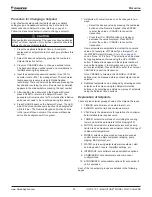
Page 16: ...leaked and that any component of the chiller may be pressurized with refrigerant Exert the proper precautions with this caveat in mind 2 Check that power has been removed from the unit Before disconne...

Page 17: ...wear on near all cool surfaces which can condense water If possible the mechanical room should be conditioned which can extend the useful lifetime for all mechanical room equipment Clearance The unit...

Page 18: ...le of draining the water from the evaporator or condenser without draining the complete system It is recommended that field installed water piping to the chiller include thermometers at the inlet and...

Page 19: ...as indicated by the MicroTech II controller Acceptable methods include the following Each of these options can be controlled by the MicroTech II or through a BAS utilizing the MicroTech II output sig...

Page 20: ...ction line Pressure Setting psi 200 225 200 Discharge Cap lb min air 75 5 84 4 6 9 Qty 1 2 1 per compressor Connection Size 1 0 inch female NPT 1 0 inch female NPT 3 8 inch flare Most codes require th...

Page 21: ...ve the part load balancing valve to the evaporator Approximate total square footage of insulation surface required for individual packaged chillers is tabulated by evaporator code Table 7 Insulation A...

Page 22: ...interconnection via pLAN however all connected chillers must share the same software revision and have the same version of chiller code WMC D is compatible for interconnection via pLAN with WMC B and...

Page 23: ...Installation www DaikinApplied com 21 IOM 1210 7 MAGNITUDE MODEL WMC CHILLERS...

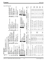
Page 24: ...IOM 1210 7 MAGNITUDE MODEL WMC CHILLERS 22 www DaikinApplied com Installation Figure 20 Wiring Index...

Page 25: ...Installation www DaikinApplied com 23 IOM 1210 7 MAGNITUDE MODEL WMC CHILLERS...

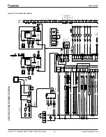
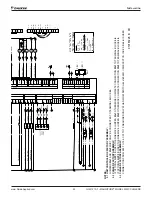
Page 26: ...IOM 1210 7 MAGNITUDE MODEL WMC CHILLERS 24 www DaikinApplied com Installation Figure 21 Controller Box Wiring...

Page 27: ...BLOCK 33 CHILLER FACTORY ASSEMBLY IF OPTIONAL GFP2 IS USED THEN REMOVE JUMPER WJ2 OTHERWISE COMPLETE CONNECTION WJ2 TO TERMINAL BLOCK 39 CHILLER FACTORY ASSEMBLY CONNECTION FROM EF0 TO 70 CF0 TO 70 RE...

Page 28: ...4 H1 941 944 954 F12 956 K1V CLOSED 30 C 2 1 24 VDC TB1 964 A2 A1 18NO 15C CTB1 875 966 967 968 M 1 t 947 S1T M1T 962 957 959 961 COM V3 963 11 12 958 14 876 K1V L1 30 K1T TD C 4 SEC K1T A2 A1 K1R A2...

Page 29: ...2 1 3 4 24 VDC 878 TB1 PS1 S 24 VAC 964 A2 A1 T3 C 18NO 15C 7 PE CTB1 875 881 167 947 962 957 959 961 COM V3 963 11 12 958 14 948 876 K1V L2 29 K1T 4 SECONDS 4 x 1S K1V L1 30 163 164 K1T K1R 5 6 TD C...

Page 30: ...enser pump start As positive Lift is developed the condenser pump is commanded to start and water flow is confirmed 5 Compressor loading As building load increases the compressor will load up maximizi...

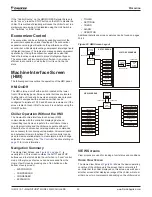
Page 31: ...ches This is the default mode This mode will ignore BAS commands 2 Local When this mode is set a STOP button and an AUTO button will appear at the top of the HMI screens as shown in Figure 24 on page...

Page 32: ...puts to the controllers It does no actual controlling and the chiller can operate without it Should the touch screen become inoperable no commands are necessary for continuing unit operation All norma...

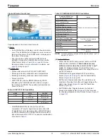
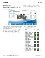
Page 33: ...hat is the device or signal that created the STATE The possible combinations are shown in Table 9 Table 9 COMPRESSOR STATUS Possibilities Complete STATUS Text in priority sequence Notes OFF Manual Swi...

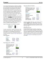
Page 34: ...all compressors is shown simultaneously on the Detail View Screen If the unit is a dual compressor unit pressing the COMP button in the lower left hand corner of the screen will generate additional st...

Page 35: ...of the startup sequence and define the compressor state at any given time Figure 27 Compressor Inputs Outputs Information The Power screen can be accessed by pressing the COMP button and will display...

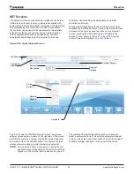
Page 36: ...sing the SET button again will toggle to the Service Screen shown in Figure 51 on page 49 A typical Setpoint Screen is displayed in Figure 30 below Figure 30 A Typical Setpoint Screen Figure 30 shows...

Page 37: ...Numeric Keypad Press ENTER to enter the value or CANCEL to cancel the transaction Press the UP or DOWN button to increase or decrease the value displayed Press ENTER to enter the value or CANCEL to c...

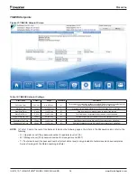
Page 38: ...me from when compressor starts to when it can start again Evap Recirculate Timer 30 sec 0 2 to 5 min M Time that evaporator pump must run before compressor start Evaporator Trip Time 12 sec 1 to 20 se...

Page 39: ...tart Surge Temp ST is compared to this SP Alarm at ST 2x SP High Discharge Temp Stop 190 F 120 to 240 F T Max discharge temp to shut down compressor High Discharge Temp Load 170 F 120 to 240 F T Sets...

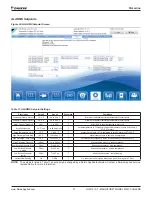
Page 40: ...Type Plate to Plate Not Used Plate to Plate Flash Tank M Specifies one of two economizer types plate to plate or flash tank if unit is equipped with economizer Economizer Open Enable 110 100 120 M Se...

Page 41: ...pe Stage EXV Control Auto 0 100 T Hold at selected percentage EXV Duration 0 sec 0 60 sec T Time the EXV position is held during staging event Start Ready Next On 1 0 1 T Configures the Ready To Start...

Page 42: ...ature or lift slope Valve Control Error Gain 20 0 to 99 T Control gain for temperature or lift error Valve Control Range Max 100 0 to 100 T Maximum valve position overrides all other settings Valve Co...

Page 43: ...t conditions for each strategy See Setting Tower Control Using the HMI Panel on page 43 for details on how to set these tower control strategies I NONE This control strategy is tower fan staging only...

Page 44: ...nd maximum values are adjustable anywhere between 0 and 100 Additional fans stage on when the VFD speed reaches the maximum value that was set V VALVE SP VFD STAGE This control strategy is tower fan c...

Page 45: ...ech II would recommend for proper head control on the WMC unit The third Analog Output Tower Reset is only configurable from the MicroTech II controller Commissioning setup of this 0 10 VDC signal tha...

Page 46: ...gain for slope The default is 1 CAUTION Setpoints 14 and 15 on the VALVE Setpoint Screen are site specific dealing with system fluid mass component size and other factors affecting the reaction of th...

Page 47: ...dataplate T RLA value from chiller data plate Maximum Amps 100 10 to 100 T RLA above which loading is inhibited Load Limit SP 5 unloads compressor Minimum Amps 40 5 to 80 T RLA below which unloading i...

Page 48: ...ler mode COOL is limited at all times by the Maximum Rate setpoint If the rate exceeds this setpoint capacity increases are inhibited Demand Limit The maximum amp draw of the compressor can be limited...

Page 49: ...k Protocol MODBUS None Local BACnet LonWorks MODBUS Remote M Sets BAS Standard Protocol to be used or LOCAL if none Condenser Pump Pump 1 Only Pump 1 Only Pump 2 Only Auto Lead 1 Primary 2 Primary M P...

Page 50: ...must be above setpoint for next compressor to start Startup Delta T 3 0 F 0 0 to 10 0 F M Degrees above setpoint for chiller to start Shutdown Delta T 3 0 F 0 0 to 3 0 F M Degrees below setpoint for c...

Page 51: ...s than or equal to 4 mA It is set equal to Heat LWT BAS set point Max Reset Delta T set point if the reset signal equals or exceeds 20 mA The Active LWT Target variable will vary linearly between thes...

Page 52: ...beled History files The Display Units button on the Operator Screen allows selection of Inch Pounds or Metric units of measure on the HMI The OPERATING MANUAL button displays the manual in Adobe SELEC...

Page 53: ...ed line which should be somewhere between the minimum and maximum motor speed lines represents the actual motor speed The Trend History Screen can display history for 24 hour 4 hour 1 hour or 15 minut...

Page 54: ...to this alarm Each alarm displays the date stamp action taken and the cause of the alarm Clicking on a listed alarm will bring up more details about that particular alarm at the top of the screen Alt...

Page 55: ...idually It is not possible to download multiple days of trend history at once To Download Alarm History Make sure that the History File text field on the right side of the Alarm History Screen shows A...

Page 56: ...e displayed See the Possible Alarms and Events section starting on page 55 for specifics on alarms that may occur After eliminating the cause of the alarm clear the alarm by pressing the CLEAR button...

Page 57: ...clears Surge High Suct SH Running Comp 2 COMPR STOP Surge Temperature Auto clears Expansion Alarm FAULT external alarm COMPR STOP Control Fault External Input Auto clears Check Valve Fault 1 CHILLER S...

Page 58: ...OAD Suction pressure Low Auto clears Ground Fault Protection 1 COMPR STOP Ground Fault Locked off requires local reset Ground Fault Protection 2 COMPR STOP Ground Fault Locked off requires local reset...

Page 59: ...TOP Compressor Fault Auto clears Pauses 20 min after 3rd alarm in 50 min Drive Fault 1 COMPR STOP Compressor Fault Auto clears Drive Fault 2 COMPR STOP Compressor Fault Auto clears Internal Control Fa...

Page 60: ...he range of the input NOT the operating range of the chiller Table 26 Controller Digital Inputs Description Signal Signal 1 Unit OFF Switch 0 VAC Stop 24 VAC Auto 2 Remote Off Enable 0 VAC Stop 24 VAC...

Page 61: ...The Password PW column indicates the password that must be active in order to change the setpoint The letters in the Password column refer to the following O Operator the password number for operator...

Page 62: ...ages 1 1 to 4 T Stage Up Time 2 min 1 to 60 min T Stage Down Time 5 min 1 to 60 min T Stage Differential Temp 3 0 F 1 0 to 10 0 F T Stage Differential Lift 6 0 psi 1 0 to 20 0 psi T Stage 1 On Temp 70...

Page 63: ...0 to 20 0 psi T Tower Reset Lift 5 0 F 0 to 10 0 F T Sensor Selection ECWT B3 ECWT B3 provided or EHRT B9 not provided T Alarms Evaporator Freeze 34 0 F 9 0 to 45 0 F T Condenser Freeze 34 0 F 9 0 to...

Page 64: ...This is particularly true when the generators are used for temporary power when the utility power is lost Generator Sizing Natural gas and diesel generators are sensitive to the compressor s locked ro...

Page 65: ...aining two bolts to enable the head to be separated from the tube sheet sufficiently for a clevis pin or hook to be inserted into an open bolt hole at the top of the head Attach a hoist to the pin or...

Page 66: ...Trend Logs O D Perform MicroTech II check log and last fault analysis X III Condenser A Confirm correct water flow and pressure drop O X B Confirm appropriate water treatment O C Clean and Leak Test...

Page 67: ...om the previous value over a rolling one minute interval Error In the context of this manual Error is the difference between the actual value of a variable and the target setting or setpoint Evaporato...

Page 68: ...e chiller s run status is continuously stored in battery backed RAM When power is returned to the compressors it checks the status of this function and if enabled it then checks if the chiller was run...

Page 69: ...ranty labor is available as set forth above such free labor does not include diagnostic visits inspections travel time and related expenses or unusual access time or costs required by product location...

Page 70: ...sold pursuant to its standard terms and conditions of sale including Limited Product Warranty Consult your local Daikin Applied representative for warranty details To find your local Daikin Applied r...

Reviews: