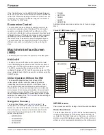
www.DaikinApplied.com 31
IOM 1210-7 • MAGNITUDE
®
MODEL WMC CHILLERS
o
peraTIon
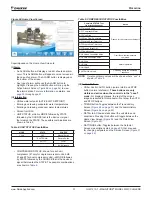
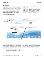
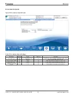
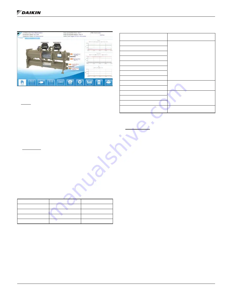
Figure 24: Home View Screen
Superimposed on the Home View Screen is:
(I) Alarm
• An ALARM button will display a red dot should an alarm
occur. This ALARM button will appear on most screens in
the case of an alarm. The ALARM button is displayed on
the bottom of the screen.
• Any type of alarm will cause the ALARM button to
highlight. Pressing the ALARM button will bring up the
Active Alarms Screen (
the alarm details. For more information on alarms, see
(II) Information
• Chilled water setpoint (ACTIVE LWT SETPOINT)
• Entering and leaving evaporator water temperatures
• Entering and leaving condenser water temperatures
• Percent unit RLA
• UNIT STATUS, which is MODE followed by STATE
followed by the SOURCE that is the device or signal
that created the STATE. The possible combinations are
shown in
.
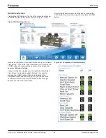
Table 8: UNIT STATUS Possibilities
MODE
STATE
SOURCE
COOL
OFF
Manual Switch
SHUTDOWN
Remote Switch
AUTO
Local
BAS Network
• COMPRESSOR STATUS, shown for each unit
compressor (#1 only for single compressor units, both
#1 and #2 for dual compressor units), is MODE followed
by STATE followed by the SOURCE that is the device or
signal that created the STATE. The possible combinations
.
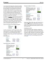
Table 9: COMPRESSOR STATUS Possibilities
Complete STATUS Text
(in priority sequence)
Notes
OFF Manual Switch
Reason for the compressor being off
OFF Compressor Alarm
OFF Unit State
OFF Evap Flow/Re-circulate
OFF Start to Start Timer=xxx
OFF Stop to Start Timer=xxx
OFF Staging (Next ON)
OFF Awaiting Load
RUN Unload Vanes-Max Amps
Overrides water temperature
command
RUN Hold Vanes-Max Amps
RUN Load
Normal operation
RUN Hold
RUN Unload
SHUTDOWN Unload
Unloading during the shutdown
sequence
NOTE:
Timer countdown values will be shown where “xxx” is
shown in
(III) Action Buttons
• Chiller Control: AUTO button (normal start) and STOP
button (normal shutdown).
These buttons are only
visible and active when the control is in the “Local”
mode.
For display purposes, the rest of the screen
images presented in this manual will not show the AUTO
and STOP buttons.
• TREND button: Toggles between the Trend History
Screen (
) and the Alarm History
Screen (
).
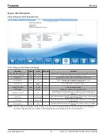
• DETAIL tab: Shows details about the unit status and
conditions. Pressing this button will toggle between the
Home View Screen (
) and the Detail View
Screen (
• SETTINGS button: Toggles between the Setpoint
Screens (descriptions start on
) that are used
for changing setpoints and the Service Screen (
).

