background image

125A7V1B

VRV IV System indoor unit

4P325971-1B – 2012.07

Installation and operation manual

17

8.

Commissioning

8.1.

Pre-operation checks

After the installation of the unit, check the following:

1

Field wiring
Make sure that the field wiring has been carried out according to
the instructions described in the chapter 

"6.3. Preparing

electrical wiring" on page 11

, according to the wiring diagrams

and according to European and national regulations.

2

Fuses and protection devices
Check that the fuses and other locally installed protection
devices are of the size and type specified in the chapter

"Electrical specifications table" on page 43

. Make sure that

neither a fuse nor a protection device has been bypassed.

3

Earth wiring
Make sure that the earth wires have been connected properly
and that the earth terminals are tightened.

4

Internal wiring
Visually check the switch box and the inside of the unit on loose
connections or damaged electrical components.

5

Installation
Check that the unit is properly installed, to avoid abnormal
noises and vibrations when starting up the unit.

6

Damaged equipment
Check the inside of the unit on damaged components or
squeezed pipes.

7

Refrigerant leak
Check the inside of the unit on refrigerant leakage. If there is a
refrigerant leak try to repair the leak (recovery, repair, and
vacuuming needed). If it is impossible to repair by yourself, call
your local dealer.
Do not touch any refrigerant which has leaked out of refrigerant
piping connections.
This may result in frostbite.

8

Vacuuming/recovery and refrigerant charging
Refer to the outdoor unit manual for more details.

9

Water leak
Check the inside of the unit on water leakage. In case there is a
water leakage try to repair the leak. If it is impossible to repair by
yourself, close the water inlet and water outlet shut-off valves
and call your local dealer.

10

Power supply voltage
Check the power supply voltage on the local supply panel. The
voltage must correspond to the voltage on the identification label
of the unit.

11

Air purge valve
Make sure the air purge valve of the heat pump is open (at least
2 turns).

12

Shut-off valves
Make sure that the shut-off valves are correctly installed and
fully open.

Once all checks are fulfilled, the unit must be closed, only then can
the unit be powered on. When the power supply to the indoor unit is
turned on, "

88

" is displayed on the user interface during its

initialization, which might take up to 30 seconds. During this process
the user interface can not be operated.

8.2.

Final air purging

To get rid of all the air in the system, the pump should be operated.

Therefore, change the field setting [E-04] as explained in the chapter

"8.3. Field settings" on page 17

. More details about setting 

"[E-04]

Pump only operation (air purge function)"

 can be found on 

page 21

.

8.3.

Field settings

The indoor unit should be configured by the installer to match the
installation environment (outdoor climate, installed options, etc.) and
user demand. Therefore, a number of so called field settings are
available. These field settings are accessible and programmable
through the user interface on the indoor unit.

Each field setting is assigned a 3-digit number or code, for example
[5-03], which is indicated on the user interface display. The first digit
[5] indicates the 'first code' or field setting group. The second and
third digit [03] together indicate the 'second code'.

A list of all field settings and default values is given in the 

"8.4. Field

setting list for Installation Manual" on page 22

. In this list we provided

2 columns to register the date and value of altered field settings at
variance with the default value.

8.3.1.

Procedure

To change one or more field settings, proceed as follows.
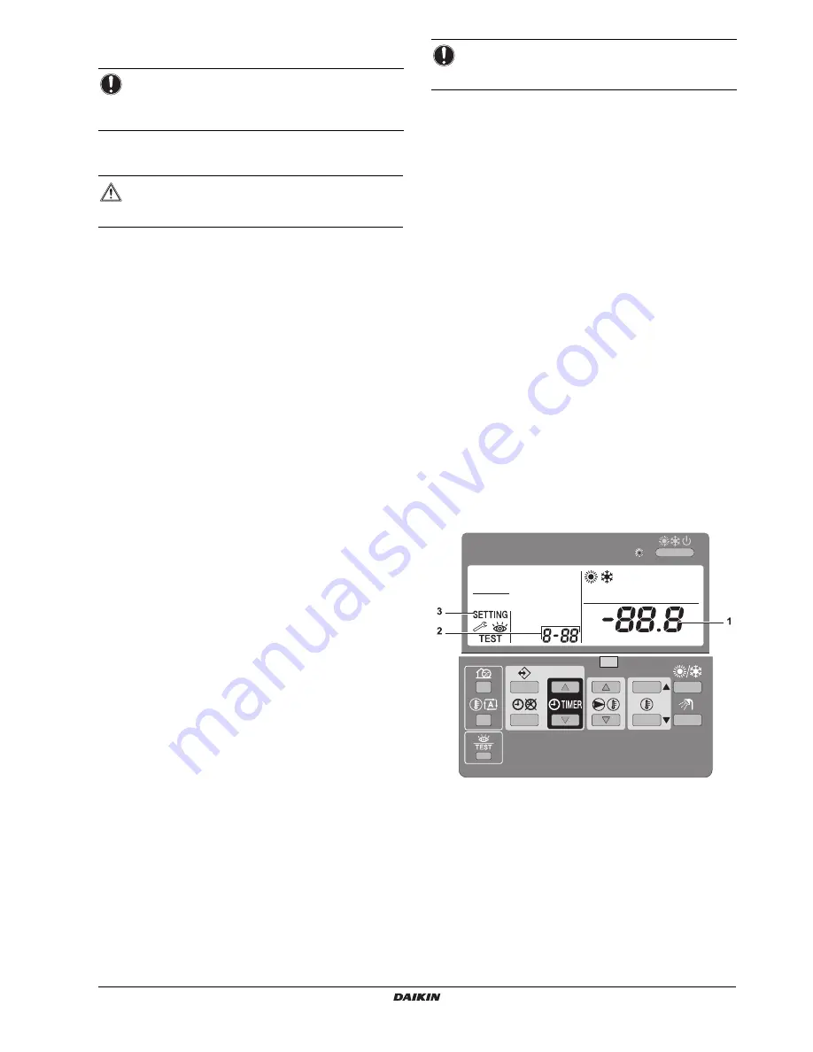
1

Press the 

z

 button for a minimum of 5 seconds to enter FIELD

SET MODE.
The 

$

 icon (3) will be displayed. The current selected

field setting code is indicated 

;

 (2), with the set value

displayed to the right 

-

 (1).

2

Press the 

ébi

 button to select the appropriate field setting

first code.

3

Press the 

ébj

 button to select the appropriate field setting

second code.

4

Press the 

pfi

 button and 

pfj

 button to change

the set value of the select field setting.

5

Save the new value by pressing the 

pr

 button.

NOTICE

It is important that all information in this chapter is read
sequentially by the installer and that the system is
configured as applicable.

WARNING

Switch off the power supply before making any
connections.

NOTICE

Operating the system with closed valves will damage the
pump!

Summary of Contents for HXY080A7V1B

Page 1: ...VRV IV System indoor unit INSTALLATION AND OPERATION MANUAL HXY080A7V1B HXY125A7V1B System indoor unit ...

Page 2: ...o positivamente por B de acuerdo con el Certificado C 06 Nota delineato nel A e giudicato positivamente da B secondo il Certificato C 07 Σημείωση όπως καθορίζεται στο A και κρίνεται θετικά από το B σύμφωνα με το Πιστοποιητικό C 08 Nota tal como estabelecido em A e com o parecer positivo de B de acordo com o Certificado C 09 Примечание как указано в A и в соответствии с положительным решением B сог...

Page 3: ...on 16 7 4 1 To fix the user interface cover to the indoor unit 16 7 4 2 To close the indoor unit 16 8 Commissioning 17 8 2 Final air purging 17 8 3 Field settings 17 8 3 1 Procedure 17 8 3 2 Detailed description 18 8 4 Field setting list for Installation Manual 22 8 5 Final check and test run 24 8 5 1 Final check 24 8 5 2 System test run 24 8 5 3 Indoor unit individual test run 24 8 6 Service and ...

Page 4: ...gerant of oil and of other parts must be done by an authorized installer and must comply with applicable legislation Units must be treated at a specialized treatment facility for reuse recycling and recovery By ensuring this product is disposed of correctly you will help to prevent potential negative consequences for the environment and human health For more information contact your installer or l...

Page 5: ...erant gas comes into contact with fire WARNING Always recover the refrigerants Do NOT release them directly into the environment Use a refrigerant reclaim unit to evacuate the installation NOTICE Make sure water quality complies with EU directive 98 83 EC DANGER RISK OF ELECTROCUTION Turn OFF all power supply before removing the switch box cover connecting electrical wiring or touching electrical ...

Page 6: ...s and or codes that are relevant and applicable for a certain product or domain Service company Qualified company which can perform or coordinate the required service to the product Installation manual Instruction manual specified for a certain product or application explaining how to install configure and maintain it Operation manual Instruction manual specified for a certain product or applicati...

Page 7: ...h Control close to the indoor unit Room thermostat functionality in the principal space to be heated Room thermostat EKRTWA EKRTR1 You can connect an optional room thermostat to the indoor unit This thermostat can either be wired EKRTWA or wireless EKRTR1 For installation instructions see the installation manual of the room thermostat Remote sensor for wireless thermostat EKRTETS You can use a wir...

Page 8: ...nit i Bypass valve field supply j User interface slave The under floor heating or heat pump connection is directly connected to the indoor unit The room temperature is controlled by the user interface which is used as room thermostat Possible installations User interface standard equipment installed in the room and used as room thermostat User interface standard equipment installed at the indoor u...

Page 9: ...nal capacity in case of heat pump capacity shortage See 9 Installing the optional EKBUHAA 6V3 6W1 heater kit on page 26 for details 6 Preparation 6 1 Preparing installation site Do NOT install the unit in places often used as work place In case of construction works e g grinding works where a lot of dust is created the unit must be covered Choose the installation location with sufficient place for...

Page 10: ... high humidity max RH 85 for example a bathroom In places where frost is possible Ambient temperature around the indoor unit should be 5 C The indoor unit is designed for indoor installation only and for indoor ambient temperatures ranging 5 35 C in cooling mode and 5 30 C in heating mode 6 2 Preparing water circuit 6 2 1 Selection of the type of heat emitters The selection of the heat emitter is ...

Page 11: ...ent galvanic corrosion Never use Zn coated parts in the water circuit Because the unit s internal water circuit uses copper piping excessive corrosion may occur Only use appropriate tooling to handle brass which is a soft material If NOT pipes will get damaged Select the water piping diameter in relation to the required water flow and the available external static pressure of the pump See 14 Techn...

Page 12: ...uit is 100 l No actions or adjustments are required Example 2 The indoor unit is installed at the highest point in the water circuit The total water volume in the water circuit is 350 l Actions Because the total water volume 350 l is more than the default water volume 280 l the pre pressure must be decreased The required pre pressure is Pg 0 3 H 10 bar 0 3 0 10 bar 0 3 bar The corresponding maximu...

Page 13: ...lectrical connections to the fixed wiring All components procured on the site and all electrical construction must comply with the applicable legislation WARNING The indoor unit should have a dedicated power supply The optional heater kit EKBUH should have a dedicated power supply 580 1 50 0 0 a b 1 a Normal power supply b Fuse 1 Power supply for indoor unit INFORMATION The following illustration ...

Page 14: ...nection Ø9 52 mm b Refrigerant gas connection Ø15 9 mm 1 Connect the liquid piping from the outdoor unit to the refrigerant liquid connection of the indoor unit 2 Connect the gas piping from the outdoor unit to the refrigerant gas connection of the indoor unit INFORMATION Installation shall be done by an installer the choice of materials and installation shall comply with the applicable legislatio...

Page 15: ...educe capacity losses during heating and cooling operations If the temperature is higher than 30 C and the humidity is higher than RH 80 the thickness of the sealing materials should be at least 20 mm to prevent condensation on the surface of the sealing NOTICE Do NOT put power on the unit before vacuuming is completed In case this happened refer to the instructions in the installation manual of t...

Page 16: ...cable legislation Use only copper wires All field wiring must be carried out in accordance with the wiring diagram supplied with the unit and the instructions given below Never squeeze bundled cables and be sure that it does not come in contact with the non insulated piping and sharp edges Be sure no external pressure is applied to the terminal connections Power supply wires must be attached secur...

Page 17: ...ce Fixation of the user interface to the indoor unit 1 Fix the wallplate of the user interface to the frontplate of the unit For installation of the frontplate see 7 4 1 To fix the user interface cover to the indoor unit on page 16 2 Cut off a 2 wire conductor 3 Connect the wires to the user interface as shown below From the rear 4 Reinstall the faceplate onto the wallplate First begin fitting fro...

Page 18: ...tening the mounting screws INFORMATION If next to the standard remote controller the optional remote controller is installed as well Connect the electrical wires of both remote controllers in the same way like described above Select a master and a slave remote controller by switching the SS1 selector switch Only the remote controller set as master can work as room thermostat INFORMATION For multip...

Page 19: ...ke sure that the shut off valves are correctly installed and fully open Once all checks are fulfilled the unit must be closed only then can the unit be powered on When the power supply to the indoor unit is turned on 88 is displayed on the user interface during its initialization which might take up to 30 seconds During this process the user interface can not be operated 8 2 Final air purging To g...

Page 20: ...g can be programmed in 2 different ways based on the temperature set point both leaving water temperature and room temperature and based on the ON OFF instruction In the following tables both methods on how to interpret the schedule timer are shown INFORMATION Changes made to a specific field setting are only stored when the pr button is pressed Navigating to a new field setting code or pressing t...

Page 21: ...D will stop working When pushing the y button The schedule timer for space heating will stop when active at that moment and will start again at the next scheduled ON function The last programmed command overrules the preceding programmed command and will remain active until the next programmed command occurs Example imagine the actual time is 17 30 and actions are programmed at 13 00 16 00 and 19 ...

Page 22: ... is installed its operation must be enabled by field setting Default 6 01 0 which means no external room thermostat is installed Set 6 01 2 if the optional external room thermostat is installed The external room thermostat only gives an ON OFF signal to the heat pump based on the room temperature Set 6 01 1 in case a heating thermostat ON or cooling thermostat ON function is required when using op...

Page 23: ...ccount influence of high ambient temperatures in the measurement 9 02 Setting is not applicable 9 03 Leaving water temperature compensation value for cooling operation 9 04 Setting not applicable A Option setup A 00 Setting is not applicable A 01 Setting is not applicable A 02 Pump target T setting heating Depending on the systems emitter type the T over the emitter can be modified within the rang...

Page 24: ...20 1 C 02 Set point at low ambient temperature Lo_Ti 40 25 80 1 C 03 Set point at high ambient temperature Hi_Ti 25 25 80 1 C 4 Settings are not applicable 00 Not applicable Do not change the default value 1 01 Not applicable Do not change the default value Fri 02 Not applicable Do not change the default value 23 00 5 Automatic setback and disinfection set point 00 Not applicable Do not change the...

Page 25: ...2 1 C 03 Set point cooling leaving water minimum temperature 10 5 18 1 C 04 Not applicable Do not change the default value 0 d Settings are not applicable 00 Not applicable Do not change the default value 10 01 Not applicable Do not change the default value 30 02 Not applicable Do not change the default value 15 03 Not applicable Do not change the default value 15 04 Not applicable Do not change t...

Page 26: ...l and u are blinking 3 Push the ba button again to leave this mode If no button is pressed the user interface leaves the display mode after 10 seconds Procedure for space heating cooling 1 Check the leaving water and entering water temperature through the user interface read out mode and write down the displayed values See Temperature read out mode on page 24 2 Push the z button 4 times so the t i...

Page 27: ...t Make sure you do not touch a conductive section Do not rinse the unit This may cause electric shocks or fire Play it safe Touch a metal part by hand such as piping sheet metal in order to eliminate static electricity and to protect the PCB before performing service Malfunction code Failure cause Corrective action A1 Failure of writing memory EEPROM malfunction Contact your local dealer A6 Malfun...

Page 28: ... heater Refer to 8 3 Field settings on page 17 how to make field settings for field settings related to the EKBUHAA heater kit Other field settings which are explained in the EKBUHAA manual are not applicable in combination with HXY 080 125 hydrobox The default values should be kept as mentioned in the installation field setting list of the HXY 080 125 hydrobox Other information which is explained...

Page 29: ...RV DX Indoor Unit Refer to outdoor unit manual for further information Push the bi or bj button Display 88 8 starts blinking Display n Set desired room temperature e g 22 C The user interface room thermostat function is not active Push the ébi or ébj button You have room temperature based control of your system user interface room thermostat is installed You have leaving water temperature based co...

Page 30: ...he system is active 16 PUMP ICON é This icon indicates that the circulation pump is active 17 OUTDOOR TEMPERATURE DISPLAY u When this icon is flashing the outdoor ambient temperature is displayed Refer to 11 3 7 Temperature read out mode on page 31 for more information 18 WEATHER DEPENDENT SET POINT ICON a This icon indicates that the controller will adapt the leaving water temperature set point a...

Page 31: ...ated as required by the room temperature set point The set point can be set manually or through the schedule timer Selecting space cooling operation 1 Use the y button to switch ON OFF space cooling c Icon c appears on the display as well as the corresponding actual room temperature The operation LED 0 lights up 2 Use the bi and bj buttons to set the desired room temperature Temperature range for ...

Page 32: ...ng set point Activating this operation will result in a lower power consumption than use with a manually fixed leaving water set point During weather dependent operation the user has the possibility to shift up or down the target water temperature by a maximum of 5 C This shift value is the temperature difference between the temperature set point calculated by the controller and the real set point...

Page 33: ...etback is started 2 02 Stop time time at which setback is stopped 5 02 Leaving water setback temperature temperature drop A Normal leaving water temperature set point B Leaving water setback temperature A 5 02 t Time T Temperature 11 3 6 Other operation modes Start up operation d During start up the d icon displays indicating that the heat pump is starting up and is not working in a steady state c...

Page 34: ...Time T Temperature set point Room temperature Leaving water temperature INFORMATION By default space cooling based on temperature set point method 1 is enabled so only temperature shifts are possible no ON OFF instruction INFORMATION By default space heating based on temperature set point method 1 is enabled so only temperature shifts are possible no ON OFF instruction Method 1 0 03 1 default Spac...

Page 35: ...t action and end with the highest number for the last action This is not a requirement but will simplify the interpretation of the program later If 2 or more actions are programmed for the same day and at the same time only the first programmed action will be executed Example You can always alter add or remove the programmed actions later INFORMATION When power returns after a power supply failure...

Page 36: ...me 8 Use the ébi and ébj buttons to set the leaving water temperature 9 Use the bi and bj buttons to set the room temperature 10 Use the ba button to select x to switch cooling and the user interface off 11 Repeat steps 6 to 10 to program the other actions When all actions have been programmed make sure that the display shows the highest action number you would like to save 12 Press the button for...

Page 37: ...e 10 Use the bi and bj buttons to set the room temperature 11 Use the ba button to select x to switch heating and the user interface off a to select automatic temperature calculation for leaving water temperature Use the ébi and ébj buttons to set the appropriate shift value refer to Setting the schedule timer on page 29 for more information about weather dependent set point 12 Repeat steps 7 to 1...

Page 38: ...lected mode is blinking You can leave programming by pressing the pr button 3 Press the button to confirm the selected mode The actual day is blinking 4 Select the day you would like to copy to the next day by means of the pi and pj buttons The selected day is blinking You can return to step 2 by pressing the pr button 5 Press the and pr buttons simultaneously for 5 seconds After 5 seconds the dis...

Page 39: ...ltered field settings at variance with the default value 11 4 1 Procedure To change one or more field settings proceed as follows 1 Press the z button for a minimum of 5 seconds to enter FIELD SET MODE The icon 3 will be displayed The current selected field setting code is indicated 2 with the set value displayed to the right 1 2 Press the ébi button to select the appropriate field setting first c...

Page 40: ...bient temperature Hi_A 15 10 20 1 C 02 Set point at low ambient temperature Lo_Ti 40 25 80 1 C 03 Set point at high ambient temperature Hi_Ti 25 25 80 1 C 4 Settings are not applicable 00 Not applicable Do not change the default value 1 01 Not applicable Do not change the default value Fri 02 Not applicable Do not change the default value 23 00 5 Automatic setback and disinfection set point 00 Not...

Page 41: ...are not applicable 00 Not applicable Do not change the default value 10 01 Not applicable Do not change the default value 30 02 Not applicable Do not change the default value 15 03 Not applicable Do not change the default value 15 04 Not applicable Do not change the default value 40 E Service mode 00 Not applicable Do not change the default value 0 01 Not applicable Do not change the default value...

Page 42: ...utton In case this procedure for resetting the safety is not successful contact your local dealer For other malfunction codes which may be displayed during the system test run or operation see the installation manual of the outdoor unit 14 Technical Data 14 1 Piping diagram a Shut off valve with drain fill valve field installed b Expansion vessel c Water filter d Safety valve 3 bar e Manometer f P...

Page 43: ...ite YLW Yellow Notes PC L N X2M C COM X1M H H20 R1H X1M X1M only for EKRTR only for EKRTETS only for EKRTW 1 C COM H 1 A6P A6P A7P X801M 4 5 1 2 3 A4P 1 A1P WHT YLW ORG BLU RED BRN BLU BRN RED BLK WHT T1R Z1F PS HAP SS1 NORM EMG HAP 3 4 X1M 5 6 X1M X1M 11 12 Cooling heating output max 0 3A 230V AC Operation on off output max 0 3A 230V AC Error output max 0 3A 230V AC L X1M N 5 X2M 6 A3P only for E...

Page 44: ...ence on DX cooling cold draft and total efficiency Heating operation a Outdoor Ta CDB WB b Indoor LWC C c Warming up zone d Normal operation range 14 5 ESP curve ESP External Static Pressure Flow Waterflow through the unit Unit ESP at 4000 rpm T 5 C Unit ESP at 3800 rpm T 8 C Maximum ESP if T 5 C heating nominal Maximum ESP if T 5 C cooling nominal NOTICE When LWE is selected 18 C optional drain p...

Page 45: ...a 79 43 Power input W 110 135 Water side Heat exchanger Type Brazed plate Quantity 1 Minimal water flow rate d d Flow switch setting l min 15 Nominal water flow rate Cooling a l min 22 9 35 8 Heating e e The sound pressure level is measured at 1 m from the unit It is a relative value depending on the distance and acoustic environment l min 25 8 40 1 Insulation material Elastomeric foam Expansion v...

Page 46: ......

Page 47: ......

Page 48: ...4P325971 1B 2012 07 Copyright 2012 Daikin ...

Reviews: