background image

11

English

NOTE

1.

The proper pressure for having nitrogen flow through the 
piping is approximately 0.02MPa, a pressure that makes 
one feel like breeze and can be obtained through a pressure 
reducing valve.

2.

Do not use flux when brazing refrigerant piping.
Use phosphor copper brazing filler metal (BCuP-2: JIS Z 
3264/B-Cu93P-710/795: ISO 3677) that does not require 
flux.
(If chlorinated flux is used, the piping will be corroded and, 
in addition if fluorine is contained, the refrigerant oil will be 
deteriorated and the refrigerant circuit will be affected 
badly.)

3.

When carrying out leakage test of refrigerant piping and the 
indoor unit after the installation of indoor unit is finished, 
confirm the connecting outdoor unit installation manual for 
test pressure.
Refer to also the outdoor unit installation manual or techni-
cal document for refrigerant piping.

4.

In case of refrigerant shortage due to forgetting additional 
refrigerant charge etc., it will result in malfunction such as 
does not cool or does not heat.
Refer to the outdoor unit installation manual or technical 
document for refrigerant piping.

CAUTION

Do not use antioxidant when brazing piping.

It may result in malfunction of components and clogging of 
piping due to residue.
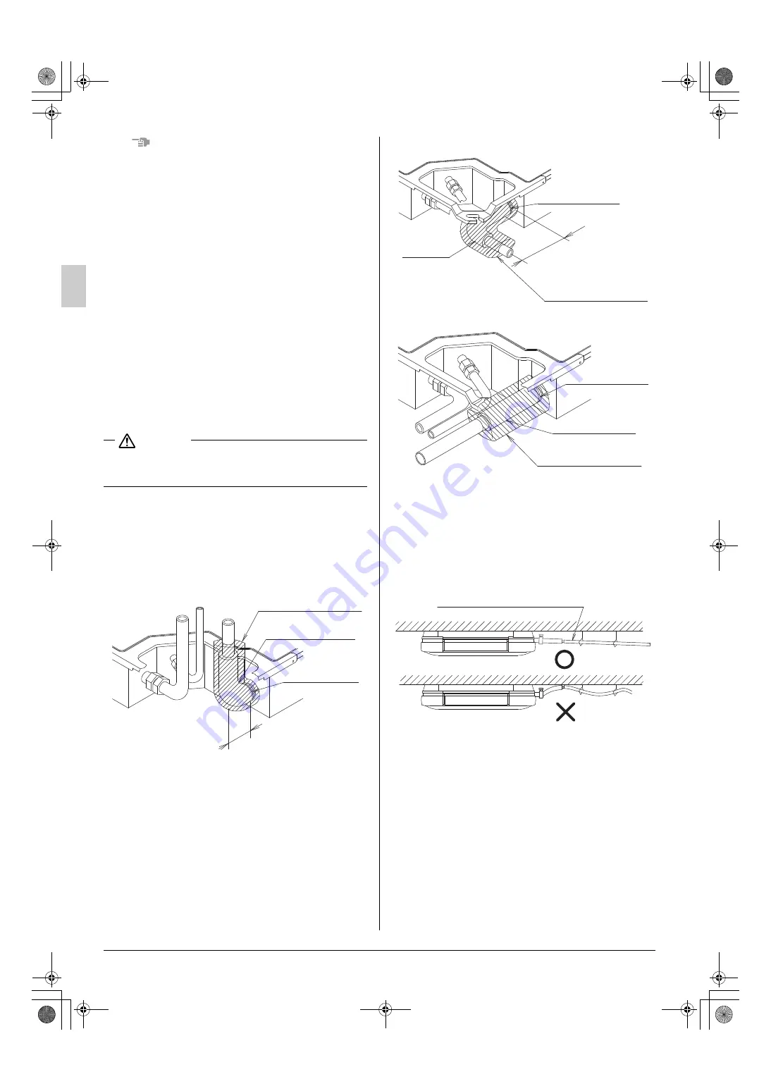
7.

DRAIN PIPING WORK

(1) Carry out drain piping.

Carry out drain piping so that drainage can ensured.

Drain piping can be connected from 3 directions. 

(Refer to Fig. 25, 26, and 27)

Select the piping diameter equal to or larger than (except 
for riser) that of the connection piping (polyvinyl chloride 
piping, nominal diameter 20mm, outside diameter 
26mm).

Install the drain piping as short as possible with down-
ward inclination of 1/100 or more and without where air 
may stagnate. 

(Refer to Fig. 28)

(It may cause abnormal sound such as bubbling noise)

Sealing material (Large) (8)
(accessory)

Elbow (10) (accessory)

Metal clamp (2)
(accessory)

Shorter side

Fig. 25
(Upward piping)

Fig. 26
(Backward piping)

Metal clamp (2)
(accessory)

Longer side

Sealing material (Large) (8)
(accessory)

Elbow (10)
(accessory)

Fig. 27
(Rightward piping)

Metal clamp (2)
(accessory)

Drain hose (1)
(accessory)

Sealing material (Large) (8)
(accessory)

Fig. 28

Downward inclination of 1/100 or more

Not acceptable

OK

01_EN_3P177351-7S.fm  Page 11  Thursday, March 21, 2013  10:19 PM

Summary of Contents for FXUQ100AVEB

Page 1: ...RE IL PRESENTE MANUALE IN UN LUOGO FACILMENTE ACCESSIBILE PER RIFERIMENTO FUTURO ΔΙΑΒΑΣΤΕ ΠΡΟΣΕΚΤΙΚΑ ΑΥΤΕΣ ΤΙΣ ΟΔΗΓΙΕΣ ΠΡΙΝ ΤΗΝ ΕΓΚΑΤΑΣΤΑΣΗ ΦΥΛΑΞΤΕ ΑΥΤΟ ΤΟ ΕΓΧΕΙΡΙΔΙΟ ΣΕ ΒΟΛΙΚΟ ΜΕΡΟΣ ΓΙΑ ΜΕΛΛΟΝΤΙΚΗ ΑΝΑΦΟΡΑ LEES DEZE INSTRUCTIES ZOGVULDIG DOOR VOORDAT MET DE INSTALLATIE WORDT BEGONNEN BEWAAR DEZE HANDLEIDING VOOR TOEKOMSTIG GEBRUIK OP EEN GESCHIKTE PLAATS ONDER HANDBEREIK LEIA ATENTAMENTE ESTAS INS...

Page 2: ...air condi tioner falling down water leakage electric shocks a fire etc Install the air conditioner on a foundation that can withstand its mass Insufficient strength may result in the air conditioner falling down and causing injury In addition it may lead to vibration of indoor units and cause unpleasant chattering noise Carry out the specified installation work in consideration of strong winds typ...

Page 3: ...llation work is R410A The air conditioner will not properly operate if a wrong refrig erant is used For installation of the outdoor unit refer to the installation manual attached to the outdoor unit Do not throw away the accessories until the installation work is completed After the indoor unit is carried into the room to avoid the indoor unit from getting damaged take measures to protect the indo...

Page 4: ...s not heat Is the insulation of refrigerant piping and drain piping com pletely carried out Water leakage Does the drain flow out smoothly Water leakage Is the power supply voltage identical to that stated in the manufacturer s label on the air conditioner Does not operate burnout Are you sure that there is no wrong wiring nor piping or no loose wiring Does not operate burnout Is earthing complete...

Page 5: ...te controller For details see the section 10 FIELD SETTING AND TEST OPERATION Caution Since there are some restriction on the piping connection side make sure to select the air dis charge pattern from the Fig 3 The names of air outlet are shown in inscription by the num ber of marks on the underside of the air outlet Refer to the Fig 4 4 Use hanging bolts for installation Investigate if the instal...

Page 6: ...grille Refer to Fig 8 Slide the two suction grille fixing knobs toward inner direction as shown by an arrow lifting upward At the same time have another person lift the tape stuck to the center of air outlet When the suction grille is opened to approximately 45 the grille can be removed from the unit Remove the 4 corner covers 835 hanging bolt pitch 835 hanging bolt pitch 950 950 unit mm Gas pipin...

Page 7: ...t the bent part 2 places at both ends of the blocking material into the clearance between the lower decoration panel and the drain pan until you hear a clicking sound When doing this work lift the end of the lower decoration panel slightly and insert the blocking material If it is difficult to insert it first loosen the screws on the both sides of the lower decoration panel and then insert it 3 In...

Page 8: ...t the hangers on the air outlet side and hang them tentatively Insert the remaining 2 hanging bolts into the hanger and fix the underside washers for the hanger 3 and the nuts Fig 12 Drain pan Lower decoration panel Insulation Projected part Blocking material Projected part Upper decoration panel 2 1 3 1 2 Insert 1 2 3 Blocking material Insert Projected part Upper decoration panel Insulation Lower...

Page 9: ... which heat resistant temperature is not less than 120 C For use under high humidity strengthen the insulation mate rial for refrigerant piping If not strengthened the surface of insulation material may sweat Before installation work make sure that the refrigerant is R410A Unless the refrigerant is R410A the normal opera tion cannot be expected CAUTION This air conditioner is a dedicated model for...

Page 10: ...ng torque sud denly increases From that position tighten the nut additionally the angle shown in Table 2 After the work is finished check securely that there is no gas leak If the nut is not tightened as instructed it may cause slow refrigerant leak and result in malfunction such as does not cool or heat Table 2 CAUTION Insulation of field piping must be carried out up to the connection inside the...

Page 11: ...rial unit side Liquid side piping insulating method Do not leave clearance Clamp 4 accessory Sealing material Small 9 accessory Flare nut connection Bring the seam to the top Wrap the sealing material from the root of the unit to the part of flare nut connection For prevention of sweating do not expose the piping Tighten the section where the piping insulating material and the joint insulating mat...

Page 12: ...efer to the outdoor unit installation manual or technical document for refrigerant piping CAUTION Do not use antioxidant when brazing piping It may result in malfunction of components and clogging of piping due to residue 7 DRAIN PIPING WORK 1 Carry out drain piping Carry out drain piping so that drainage can ensured Drain piping can be connected from 3 directions Refer to Fig 25 26 and 27 Select ...

Page 13: ...rs more than the width of metal clamp 2 leaving 10 15 mm from the tip of the elbow 10 without wrapping as shown in Fig 30 2 Insert the drain hose 1 and the elbow 10 to the root of the drain socket Tighten the metal clamp 2 within the taped range of hose inserted tip with the torque 1 35 0 15N m 135 15N cm Refer to Fig 25 26 27 and 31 Do not tighten the metal clamp 2 with the torque more than the s...

Page 14: ...ontrol box lid and connect the single phase power supply to the terminal L N on the terminal block X2M Connect the earth wiring to the earth terminal Refer to Fig 35 2 Make sure the control box lid is closed before turning on the power supply Fig 32 1 Section A A of Fig 31 Tightened part In case of bending the tip approx 90 Bend the tip without tearing the sealing material Large 8 Fig 32 2 Section...

Page 15: ...installation manual attached to the remote controller Do not touch the Printed Circuit Board assembly It may cause malfunction 8 2 ELECTRICAL CHARACTERISTICS MCA Min Circuit Amps A MFA Max Fuse Amps A kW Fan Motor Rated Output kW FLA Full Load Amps A 8 3 SPECIFICATION FOR FIELD SUPPLIED FUSES AND WIRING The lengths of remote controller wiring and transmission wiring are as follows 1 Remote control...

Page 16: ...nd transmission wiring 0 88 0 08 Terminal for power supply 1 47 0 14 Earth terminal 1 47 0 14 Non woven fabric 15 Start sticking from the radius ending line Non woven fabric 15 sticking method Power supply terminal block X2M Fig 38 Terminal block for remote controller transmission wiring X1M Power supply terminal block X2M Clamp 4 accessory Remote controller wiring Transmission wiring Power supply...

Page 17: ...is used for 1 indoor unit No 2 system When carrying out group control or 2 remote controllers control No 3 system When BS unit is used NOTE Remote controller wiring and transmission wiring do not have polarity WARNING Be sure to install an earth leakage circuit breaker Failure to do so may cause electric shocks and a fire Sealing material Small 9 Remote controller transmission wiring Power supply ...

Page 18: ...ted to the remote controller 8 8 FOR REMOTE CONTROL FORCED OFF OR ON OFF OPERATION 1 Wiring method and specification Remote control is available by connecting the external input to the terminals T1 and T2 on the terminal block for remote controller and transmission wiring 2 Actuation Input A of FORCED OFF and ON OFF OPERATION will be as the table shown below 3 How to choose FORCED OFF or ON OFF OP...

Page 19: ...AUTION Before carrying out field setting check the items mentioned in the clause 2 1 Items to be checked after the installation work is completed on page 3 Check if all the installation and piping works for the air condi tioner are completed Check if the control box lids of the air conditioner are closed Fig 45 Piping penetrating place Piping penetrating place Cut with saw blade Cut with a saw bla...

Page 20: ...ual attached to the wireless remote controller 10 4 SETTING FAN SPEED DURING THERMOSTAT OFF Set the fan speed according to the using environment after consultation with your customer When the fan speed is changed explain the fan speed rate to your customer Table 4 10 5 SETTING FILTER SIGN A message to inform the air filter cleaning time will be indi cated on the remote controller Set the SECOND CO...

Page 21: ... and leakage To the operator carrying out test operation After test operation is completed before delivering the air conditioner to the customer confirm that the control box lid is closed In addition explain the power supply status power supply ON OFF to the customer 11 WIRING DIAGRAM Refer to Fig 48 Remote controller indication Details Though the central ized control is not carried out the lamp t...

Page 22: ...H WIRELESS ADDRESS SET R1T CONNECTOR WIRELESS REMOTE CONTROLLER CONNECTOR POWER SUPPLY FOR ADAPTOR X24A X35A WIRING DIAGRAM WIRELESS REMOTE CONTROLLER RECEIVER DISPLAY UNIT INDOOR UNIT 2 IN CASE USING CENTRAL REMOTE CONTROLLER CONNECT IT TO THE UNIT IN ACCORDANCE WITH THE ATTACHED INSTALLATION MANUAL 3 IN CASE OF MAIN SUB CHANGEOVER SEE THE INSTALLATION MANUAL ATTACHED TO REMOTE CONTROLLER 4 SYMBO...

Page 23: ... 1303 HT 3P177351 7S EM12A004A 00_CV_3P177351 7S fm Page 2 Friday March 8 2013 5 15 PM ...

Reviews: