background image

4 About the system

Installation and operation manual

8

FXFA20~125A2VEB

VRV system air conditioner

3P599604-1C – 2020.10

▪ Be aware that the refrigerant inside

the system is odourless.

WARNING

The refrigerant inside the unit is mildly
flammable, but normally does NOT
leak. If the refrigerant leaks in the room
and comes in contact with fire from a
burner, a heater, or a cooker, this may
result in fire, or the formation of a
harmful gas.

Turn off any combustible heating
devices, ventilate the room, and
contact the dealer where you
purchased the unit.

Do NOT use the unit until a service
person confirms that the part from
which the refrigerant leaked has been
repaired.

WARNING

It is necessary to replace the sensor
after every detection or at the end of
the lifetime. Authorized person only
MUST replace the sensor.

WARNING

The appliance shall be stored in a
room without continuously operating
ignition sources (example: open
flames, an operating gas appliance or
an operating electric heater).

Troubleshooting (see 

"8 Troubleshooting" 

[

4

 12])

WARNING

Stop operation and shut off the
power if anything unusual occurs
(burning smells etc.).

Leaving the unit running under such
circumstances may cause breakage,
electric shock or fire. Contact your
dealer.

4

About the system

WARNING

▪ Do  NOT  modify,  disassemble,  remove,  reinstall  or

repair  the  unit  yourself  as  incorrect  dismantling  or
installation may cause an electric shock or fire. Contact
your dealer.

▪ In case of accidental refrigerant leaks, make sure there

are  no  naked  flames.  The  refrigerant  itself  is  entirely
safe,  non-toxic  and  mildly  flammable,  but  it  will
generate  toxic  gas  when  it  accidentally  leaks  into  a
room  where  combustible  air  from  fan  heaters,  gas
cookers,  etc.  is  present.  Always  have  qualified  service
personnel  confirm  that  the  point  of  leakage  has  been
repaired or corrected before resuming operation.

NOTICE

Do  NOT  use  the  system  for  other  purposes.  In  order  to
avoid  any  quality  deterioration,  do  NOT  use  the  unit  for
cooling  precision  instruments,  food,  plants,  animals,  or
works of art.

NOTICE

For future modifications or expansions of your system:

A  full  overview  of  allowable  combinations  (for  future
system  extensions)  is  available  in  technical  engineering
data  and  should  be  consulted.  Contact  your  installer  to
receive more information and professional advice.

CAUTION

This  unit  is  equipped  with  electrically  powered  safety
measures,  such  as  a  refrigerant  leak  detector.  In  order  to
be  effective,  the  unit  must  be  electrically  powered  at  all
times after installation, except for short service periods.

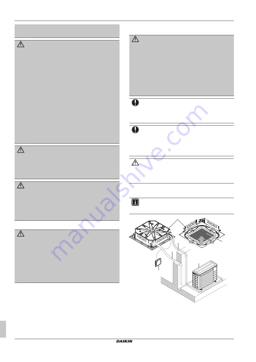
4.1

System layout

INFORMATION

The  following  illustration  is  an  example  and  might  NOT
match your system layout.

a

b

c

d

e

h

f

a

Indoor unit

b

Outdoor unit

c

User interface

d

Suction air

e

Discharge air

f

Refrigerant transmission cable

g

Drain pipe

h

Suction grille and air filter

Summary of Contents for FXFA100A2VEB

Page 1: ...eration manual VRV system air conditioner English Installation and operation manual VRV system air conditioner FXFA20A2VEB FXFA25A2VEB FXFA32A2VEB FXFA40A2VEB FXFA50A2VEB FXFA63A2VEB FXFA80A2VEB FXFA100A2VEB FXFA125A2VEB ...

Page 2: ... fie utilizate în conformitate cu instrucţiunile noastre skladni z naslednjimi standardi in drugimi normativi pod pogojem da se uporabljajo v skladu z našimi navodili on vastavuses järgmis t e standardi te ga või teiste normatiivsete dokumentidega kui neid kasutatakse vastavalt meie juhenditele съответстват на следните стандарти или други нормативни документи при условие че се използват съгласно н...

Page 3: ... wiring components 18 14 2 To connect the electrical wiring to the indoor unit 18 15 Commissioning 19 15 1 Checklist before commissioning 19 15 2 To perform a test run 19 16 Configuration 19 16 1 Field setting 19 17 Technical data 21 17 1 Wiring diagram 21 17 1 1 Unified wiring diagram legend 21 1 About the documentation 1 1 About this document Target audience Authorised installers end users INFOR...

Page 4: ...per earthing Do NOT earth the unit to a utility pipe surge absorber or telephone earth Incomplete earthing may cause electrical shock Install the required fuses or circuit breakers Secure the electrical wiring with cable ties so that the cables do NOT come in contact with sharp edges or piping particularly on the high pressure side Do NOT use taped wires stranded conductor wires extension cords or...

Page 5: ...on piping Protection devices piping and fittings shall be protected as far as possible against adverse environmental effects Provision shall be made for expansion and contraction of long runs of piping Piping in refrigerating systems shall be designed and installed such as to minimise the likelihood of hydraulic shock damaging the system The indoor equipment and pipes shall be securely mounted and...

Page 6: ...bol means that the battery contains a heavy metal above a certain concentration Possible chemical symbols are Pb lead 0 004 Waste batteries must be treated at a specialized treatment facility for reuse By ensuring waste batteries are disposed of correctly you will help to prevent potential negative consequences for the environment and human health 3 2 Instructions for safe operation WARNING Do NOT...

Page 7: ...ting any maintenance task CAUTION Do NOT insert fingers rods or other objects into the air inlet or outlet When the fan is rotating at high speed it will cause injury WARNING NEVER replace a fuse with a fuse of a wrong ampere ratings or other wires when a fuse blows out Use of wire or copper wire may cause the unit to break down or cause a fire CAUTION After a long use check the unit stand and fit...

Page 8: ...he unit yourself as incorrect dismantling or installation may cause an electric shock or fire Contact your dealer In case of accidental refrigerant leaks make sure there are no naked flames The refrigerant itself is entirely safe non toxic and mildly flammable but it will generate toxic gas when it accidentally leaks into a room where combustible air from fan heaters gas cookers etc is present Alw...

Page 9: ...ooling Heating and Auto operation modes Setback A function that keeps the room temperature in a specific range when the system is turned off by the user the schedule function or the OFF timer 6 2 1 Basic operation modes The indoor unit can operate in various operation modes Icon Operation mode Cooling In this mode cooling will be activated as required by the setpoint or by Setback operation Heatin...

Page 10: ...fan is rotating at high speed it will cause injury NOTICE NEVER inspect or service the unit by yourself Ask a qualified service person to perform this work However as end user you may clean the air filter suction grille air outlet and outside panels WARNING NEVER replace a fuse with a fuse of a wrong ampere ratings or other wires when a fuse blows out Use of wire or copper wire may cause the unit ...

Page 11: ...er interface 7 2 2 To clean the suction grille NOTICE Do NOT use water of 50 C or higher Possible consequence Discoloration and deformation 1 Open the suction grille Standard panel 1 Design panel 1 1 2 2 2 Remove the suction grille Standard panel 45 1 2 Design panel 1 2 3 Remove the air filter 1 2 3 4 Clean the suction grille Wash with a soft bristle brush and water or neutral detergent If the suc...

Page 12: ...time Authorized person only MUST replace the sensor NOTICE Functionality of the safety measures are periodically automatically checked In case of malfunction error code will display on the user interface NOTICE The R32 refrigerant leakage sensor is a semiconductor detector which may incorrectly detect substances other than R32 refrigerant Avoid using chemical substances e g organic solvents hair s...

Page 13: ...ntling of the system treatment of the refrigerant oil and other parts MUST comply with applicable legislation Units MUST be treated at a specialised treatment facility for reuse recycling and recovery For the installer 11 About the box 11 1 Indoor unit 11 1 1 To remove the accessories from the indoor unit 1 1 1 8 4 1 1 1 a 4 1 1 7 e f d c b h i m g j k l a Paper pattern for installation upper part...

Page 14: ...tion before installation Minimum floor area requirements CAUTION The total refrigerant charge in the system cannot exceed the requirements for minimum floor area of the smallest room that is served For minimum floor area requirements for indoor units see the installation and operation manual of the outdoor unit 12 2 Mounting the indoor unit 12 2 1 Guidelines when installing the indoor unit INFORMA...

Page 15: ...ine the correct vertical position 2 1 2 1 2 1 2 1 A B 1 1 2 C a b c 2 1 2 D A In case of installation with standard decoration panel B In case of installation with fresh air intake kit C In case of installation with self cleaning decoration panel D In case of installation with design decoration panel a Suspended ceiling b Installation guide accessory c Unit Level Make sure the unit is level at all...

Page 16: ...is less than 4 mm from the metal clamp part 3 Check for water leaks see To check for water leaks 416 4 Install the insulation piece drain pipe 5 Wind the large sealing pad insulation around the metal clamp and drain hose and fix it with tie wraps 6 Connect the drain piping to the drain hose 4 mm A A A A A A f 6 5 2 c e 4 b a d b a d c 3 1 2 6 1 a Drain pipe connection attached to the unit b Drain ...

Page 17: ...rial Phosphoric acid deoxidised seamless copper Flare connections Only use annealed material Piping temper grade and thickness Outer diameter Ø Temper grade Thickness t a 6 4 mm 1 4 Annealed O 0 8 mm t Ø 9 5 mm 3 8 12 7 mm 1 2 15 9 mm 5 8 a Depending on the applicable legislation and the maximum working pressure of the unit see PS High on the unit name plate larger piping thickness might be requir...

Page 18: ...current device Must comply with applicable legislation a MCA Minimum circuit ampacity Stated values are maximum values see electrical data of indoor unit for exact values 14 2 To connect the electrical wiring to the indoor unit NOTICE Follow the wiring diagram delivered with the unit located at the inside of the service cover For instructions on how to connect the optional equipment see the instal...

Page 19: ...e system is properly earthed and the earth terminals are tightened The fuses or locally installed protection devices are installed according to this document and have NOT been bypassed The power supply voltage matches the voltage on the identification label of the unit There are NO loose connections or damaged electrical components in the switch box There are NO damaged components or squeezed pipe...

Page 20: ...tion in the room It determines the interval at which Time to clean filter notification is displayed on the user interface If you want an interval of air contamination Then 1 M SW 2500 h light 10 20 0 01 1250 h heavy 02 Notification ON 3 01 Notification OFF 02 Setting Thermostat sensor selection This setting must correspond with how if the remote controller thermostat sensor is used When the remote...

Page 21: ... earth Connection Protective earth screw Connector A Rectifier Earth Relay connector Field wiring Short circuit connector Fuse Terminal INDOOR Indoor unit Terminal strip Symbol Meaning Symbol Meaning OUTDOOR Outdoor unit Wire clamp Residual current device Symbol Colour Symbol Colour BLK Black ORG Orange BLU Blue PNK Pink BRN Brown PRP PPL Purple GRN Green RED Red GRY Grey WHT White YLW Yellow Symb...

Page 22: ...G Refrigerant leak detector S NPH Pressure sensor high S NPL Pressure sensor low S PH HPS Pressure switch high S PL Pressure switch low S T Thermostat S RH Humidity sensor S W SW Operation switch SA F1S Surge arrester SR WLU Signal receiver SS Selector switch SHEET METAL Terminal strip fixed plate T R Transformer TC TRC Transmitter V R V Varistor V R Diode bridge Insulated gate bipolar transistor ...

Page 23: ......

Page 24: ...3P599604 1C 2020 10 Copyright 2020 Daikin Verantwortung für Energie und Umwelt ...

Reviews: