background image

5 Installation

Installation and operation manual

9

FFA25~60A2VEB
Split system air conditioners
4P456960-1 – 2017.03

Piping size

(mm)

Tightening

torque (N•m)

Flare

dimensions (A)

(mm)

Flare shape

(mm)

Ø6.4

15~17

8.7~9.1

R=0.4~0.8

45° ±2

90°±2

A

Ø9.5

33~39

12.8~13.2

Ø12.7

50~60

16.2~16.6

5.2.4

Pipe bending guidelines

Use  a  pipe  bender  for  bending.  All  pipe  bends  should  be  as  gentle
as possible (bending radius should be 30~40 mm or larger).

5.2.5

To flare the pipe end

CAUTION

▪ Incomplete flaring may cause refrigerant gas leakage.

▪ Do  NOT  re-use  flares.  Use  new  flares  to  prevent

refrigerant gas leakage.

▪ Use  flare  nuts  that  are  included  with  the  unit.  Using

different flare nuts may cause refrigerant gas leakage.

1

Cut the pipe end with a pipe cutter.

2

Remove  burrs  with  the  cut  surface  facing  down  so  that  the
chips do not enter the pipe.

a

b

a

Cut exactly at right angles.

b

Remove burrs.

3

Remove  the  flare  nut  from  the  stop  valve  and  put  the  flare  nut
on the pipe.

4

Flare  the  pipe.  Set  exactly  at  the  position  as  shown  in  the
following illustration.

A

Flare tool for

R410A or R32

(clutch type)

Conventional flare tool

Clutch type

(Ridgid-type)

Wing nut type

(Imperial-type)

A

0~0.5 mm

1.0~1.5 mm

1.5~2.0 mm

5

Check that the flaring is properly made.

a

b

c

a

Flare’s inner surface must be flawless.

b

The pipe end must be evenly flared in a perfect circle.

c

Make sure the flare nut is fitted.

5.2.6

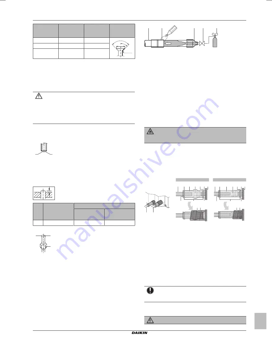
To braze the pipe end

The  indoor  unit  and  outdoor  unit  have  flare  connections.  Connect
both  ends  without  brazing.  If  brazing  should  be  needed,  take  the
following into account:

▪ When  brazing,  blow  through  with  nitrogen  to  prevent  creation  of

large  quantities  of  oxidised  film  on  the  inside  of  the  piping.  This
film adversely affects valves and compressors in the refrigerating
system and prevents proper operation.

▪ Set  the  nitrogen  pressure  to  20  kPa  (0.2  bar)  (just  enough  so  it

can be felt on the skin) with a pressure-reducing valve.

a

b

c

d

e

f

f

a

Refrigerant piping

b

Part to be brazed

c

Taping

d

Manual valve

e

Pressure-reducing valve

f

Nitrogen

▪ Do NOT use anti-oxidants when brazing pipe joints.

Residue can clog pipes and break equipment.

▪ Do  NOT  use  flux  when  brazing  copper-to-copper  refrigerant

piping.  Use  phosphor  copper  brazing  filler  alloy  (BCuP),  which
does not require flux.
Flux  has  an  extremely  harmful  influence  on  refrigerant  piping
systems. For instance, if chlorine based flux is used, it will cause
pipe  corrosion  or,  in  particular,  if  the  flux  contains  fluorine,  it  will
deteriorate the refrigerant oil.

5.2.7

To connect the refrigerant piping to the
indoor unit

WARNING: FLAMMABLE MATERIAL

The  R32  refrigerant  (if  applicable)  in  this  unit  is  mildly
flammable.

(a)

(a)

Refer to the outdoor unit specifications for the type of
refrigerant to be used.

Pipe length

. Keep refrigerant piping as short as possible.

Flare  connections

.  Connect  refrigerant  piping  to  the  unit  using

flare connections.

Insulation

.  Insulate  the  refrigerant  piping  on  the  indoor  unit  as

follows:

A

B

a

d

c

e f

b

b

a

d

c

e f

b

b

2

4

3

g

1

2

3

4

g

A

B

1

A

Gas piping

B

Liquid piping

a

Insulation material (field supply)

b

Cable tie (accessory)

c

Insulation pieces: Large (gas pipe), small (liquid pipe)
(accessories)

d

Flare nut (attached to the unit)

e

Refrigerant pipe connection (attached to the unit)

f

Unit

g

Sealing pads: Medium 1 (gas pipe), medium 2 (liquid pipe)
(accessories)

1

Turn up the seams of the insulation pieces.

2

Attach to the base of the unit.

3

Tighten the cable ties on the insulation pieces.

4

Wrap the sealing pad from the base of the unit to the top of
the flare nut.

NOTICE

Make  sure  to  insulate  all  refrigerant  piping.  Any  exposed
piping might cause condensation.

5.3

Connecting the electrical wiring

DANGER: RISK OF ELECTROCUTION

Summary of Contents for FFA25A2VEB

Page 1: ...Installation and operation manual Split system air conditioners English Installation and operation manual Split system air conditioners FFA25A2VEB FFA35A2VEB FFA50A2VEB FFA60A2VEB ...

Page 2: ...mitate cu instrucţiunile noastre skladni z naslednjimi standardi in drugimi normativi pod pogojem da se uporabljajo v skladu z našimi navodili on vastavuses järgmis t e standardi te ga või teiste normatiivsete dokumentidega kui neid kasutatakse vastavalt meie juhenditele съответстват на следните стандарти или други нормативни документи при условие че се използват съгласно нашите инструкции atitink...

Page 3: ...e heating operation 16 12 2 4 To operate the system 16 12 3 Using the dry program 16 12 3 1 About the dry program 16 12 3 2 To use the dry program 16 12 4 Adjusting the air flow direction 16 12 4 1 About the air flow flap 16 13 Maintenance and service 17 13 1 Cleaning the air filter suction grille air outlet and outside panels 17 13 1 1 To clean the air filter 17 13 1 2 To clean the suction grille...

Page 4: ... precautions c Indoor unit installation and operation manual d Washers for hanger bracket e Screws f Cable ties g Metal clamp h Sealing pads Large drain pipe medium 1 gas pipe medium 2 liquid pipe small electrical wiring i Drain hose j Insulation piece Small liquid pipe k Insulation piece Large gas pipe 3 About the units and options 3 1 About the indoor unit Use the system in the following tempera...

Page 5: ...l is less than 70 dBA CAUTION Appliance not accessible to the general public install it in a secured area protected from easy access This unit both indoor and outdoor is suitable for installation in a commercial and light industrial environment Spacing Mind the following requirements mm 1500 1500 2000 4000 1500 A B C b a d a c A Minimum distance to the wall B Minimum and maximum distance to the fl...

Page 6: ...ning is within the following limits Minimum 585 mm to be able to fit the unit Maximum 660 mm in case of installation with BYFQ60B and 595 mm in case of installation with BYFQ60C ensure enough overlapping between the decoration panel and the suspended ceiling If the ceiling opening is larger add extra ceiling material Make sure the unit and its hanger brackets suspension are centered within the cei...

Page 7: ...ipes Make sure to use drain pipes and T joints with the correct gauge for the operating capacity of the units 100 A mm a A 645 mm In case of installation with BYFQ60B 630 mm In case of installation with BYFQ60C a T joint To connect the drain piping to the indoor unit NOTICE Incorrect connection of the drain hose might cause leaks and damage the installation space and surroundings 1 Push the drain ...

Page 8: ... through the air discharge outlet and check for leaks see When electrical wiring is not finished yet 5 2 Connecting the refrigerant piping DANGER RISK OF BURNING 5 2 1 About connecting the refrigerant piping Before connecting the refrigerant piping Make sure the outdoor and indoor unit are mounted Typical workflow Connecting the refrigerant piping involves Connecting the refrigerant piping to the ...

Page 9: ...efrigerating system and prevents proper operation Set the nitrogen pressure to 20 kPa 0 2 bar just enough so it can be felt on the skin with a pressure reducing valve a b c d e f f a Refrigerant piping b Part to be brazed c Taping d Manual valve e Pressure reducing valve f Nitrogen Do NOT use anti oxidants when brazing pipe joints Residue can clog pipes and break equipment Do NOT use flux when bra...

Page 10: ...ectrical wiring on the indoor unit NOTICE Follow the wiring diagram delivered with the unit located at the inside of the service cover For instructions on how to connect the decoration panel and the sensor kit see the wiring instruction sheet delivered with the unit inside the accessory bag Make sure the electrical wiring does NOT obstruct proper reattachment of the service cover It is important t...

Page 11: ...eating operation LL2 Monitoring 12 12 22 3 01 Setup volume2 Monitoring 22 02 Setting Time to clean air filter This setting must correspond with the air contamination in the room It determines the interval at which the TIME TO CLEAN AIR FILTER notification is displayed on the user interface When using a wireless user interface you must also set the address see the installation manual of the user in...

Page 12: ...y earthed and the earth terminals are tightened The fuses or locally installed protection devices are installed according to this document and have not been bypassed The power supply voltage matches the voltage on the identification label of the unit There are NO loose connections or damaged electrical components in the switch box The insulation resistance of the compressor is OK There are NO dama...

Page 13: ...ply and outdoor unit between outdoor unit and indoor units between indoor unit and user interface The fuse on the outdoor or indoor unit PCB has blown E3 E4 or L8 The stop valves are closed The air inlet or air outlet is blocked E7 There is a missing phase in case of three phase power supply units Note Operation will be impossible Turn OFF the power recheck the wiring and switch two of the three e...

Page 14: ... OVERLOADPROTECTOR D V D DIODE Q M THERMOSWITCH DB DIODEBRIDGE R RESISTOR DS DIPSWITCH R T THERMISTOR E H HEATER RC RECEIVER F U FU FORCHARACTERISTICS REFERTOPCBINSIDEYOURUNIT FUSE S C LIMITSWITCH FG CONNECTOR FRAMEGROUND S L FLOATSWITCH H HARNESS S NPH PRESSURESENSOR HIGH H P LED V L PILOTLAMP LIGHTEMITTINGDIODE S NPL PRESSURESENSOR LOW HAP LIGHTEMITTINGDIODE SERVICEMONITORGREEN S PH HPS PRESSURE...

Page 15: ...e main functions of the system For more information about the user interface see the operation manual of the installed user interface 12 Operation 12 1 Operation range Use the system in the following temperature and humidity ranges for safe and effective operation For combination with R410A outdoor unit refer to the following table Outdoor units Cooling Heating RR71 125 Outdoor temperature 15 46 C...

Page 16: ...e indoor fan is automatically stopped The display of the user interface shows It may take some time before the fan starts This is not a malfunction 12 2 4 To operate the system 1 Press the operation mode selector button on the user interface several times and select the operation mode of your choice Cooling operation Heating operation Fan only operation 2 Press the ON OFF button on the user interf...

Page 17: ...ueeze it well and wipe the panel clean Wipe it with another dry cloth CAUTION Before accessing terminal devices make sure to interrupt all power supply NOTICE When cleaning the heat exchanger make sure to remove the switch box fan motor drain pump and float switch Water or detergent might deteriorate the insulation of electronic components and result in burnout of these components 13 1 Cleaning th...

Page 18: ...lean the air filter on page 17 and 13 1 3 To clean the air outlet and outside panels on page 18 Turn on the power at least 6 hours before operating the unit in order to ensure smoother operation As soon as the power is turned on the user interface display appears 13 3 Maintenance before a long stop period E g at the end of the season Let the indoor units run in fan only operation for about half a ...

Page 19: ...irely safe and non toxic R410A is a non combustible refrigerant and R32 is a mildly flammable refrigerant but they will generate a toxic gas when they accidentally leak into a room where combustible air from fan heaters gas cookers etc is present Always have qualified service personnel confirm that the point of leakage has been repaired or corrected before resuming operation 13 5 3 Recommended mai...

Page 20: ... indoor unit is not blocked by obstacles Remove any obstacles and make sure the air can flow freely Check if the air filter is not clogged see 13 1 1 To clean the air filter on page 17 Check the temperature setting Check the fan speed setting on your user interface Check for open doors or windows Close doors and windows to prevent wind from coming in Check if there are too many occupants in the ro...

Page 21: ... and contraction of plastic parts caused by temperature change make this noise 14 1 8 Symptom Noise of air conditioners Indoor unit outdoor unit A continuous low hissing sound is heard when the system is in cooling or defrost operation This is the sound of refrigerant gas flowing through both indoor and outdoor units A hissing sound which is heard at the start or immediately after stopping operati...

Page 22: ......

Page 23: ......

Page 24: ...4P456960 1 2017 03 Copyright 2017 Daikin ...

Reviews: