background image

Operation manual

5

EWWP014~065KBW1N

Packaged water-cooled water chillers

4PW61660-1A – 04.2012

B

EFORE


OPERATION

Checks before initial start-up 

After the installation of the unit, check the following before switching
on the circuit breaker:

1

Field wiring

Make sure that the field wiring between the local supply panel
and the unit has been carried out according to the instructions
described in the installation manual, according to the wiring
diagrams and according to European and national regulations.

2

Fuses or protection devices

Check that the fuses or the locally installed protection devices
are of the size and type specified in the installation manual.
Make sure that neither a fuse nor a protection device has been
bypassed.

3

Earth wiring

Make sure that the earth wires have been connected properly
and that the earth terminals are tightened.

4

Internal wiring

Visually check the switch box on loose connections or damaged
electrical components.

5

Fixation

Check that the unit is properly fixed, to avoid abnormal noises
and vibrations when starting up the unit.

6

Damaged equipment

Check the inside of the unit on damaged components or
squeezed pipes.

7

Refrigerant leak

Check the inside of the unit on refrigerant leakage. If there is a
refrigerant leak, call your local dealer.

8

Oil leak

Check the compressor on oil leakage. If there is an oil leak, call
your local dealer.

9

Power supply voltage

Check the power supply voltage on the local supply panel. The
voltage should correspond to the voltage on the identification
label of the unit.

Water supply

Fill the water piping, taking into account the minimum water
volume required by the unit. Refer to the chapter "Water charge, flow
and quality"


in the installation manual.

Make sure that the water is of the quality as mentioned in the
installation manual.

Purge the air at the high points of the system and check the operation
of the circulation pump and the flow switch.

General recommendations

Before switching on the unit, read following recommendations:

1

When the complete installation and all necessary settings have
been carried out, close all front panels of the unit.

2

The service panel of the switch box may only be opened by a
licensed electrician for maintenance purposes.

O

PERATION

The EWWP units are equipped with a digital controller offering a
user-friendly way to set up, use and maintain the unit.

This part of the manual has a task-oriented, modular structure. Apart
from the first section, which gives a brief description of the controller
itself, each section or subsection deals with a specific task you can
perform with the unit.

Digital controller

User interface

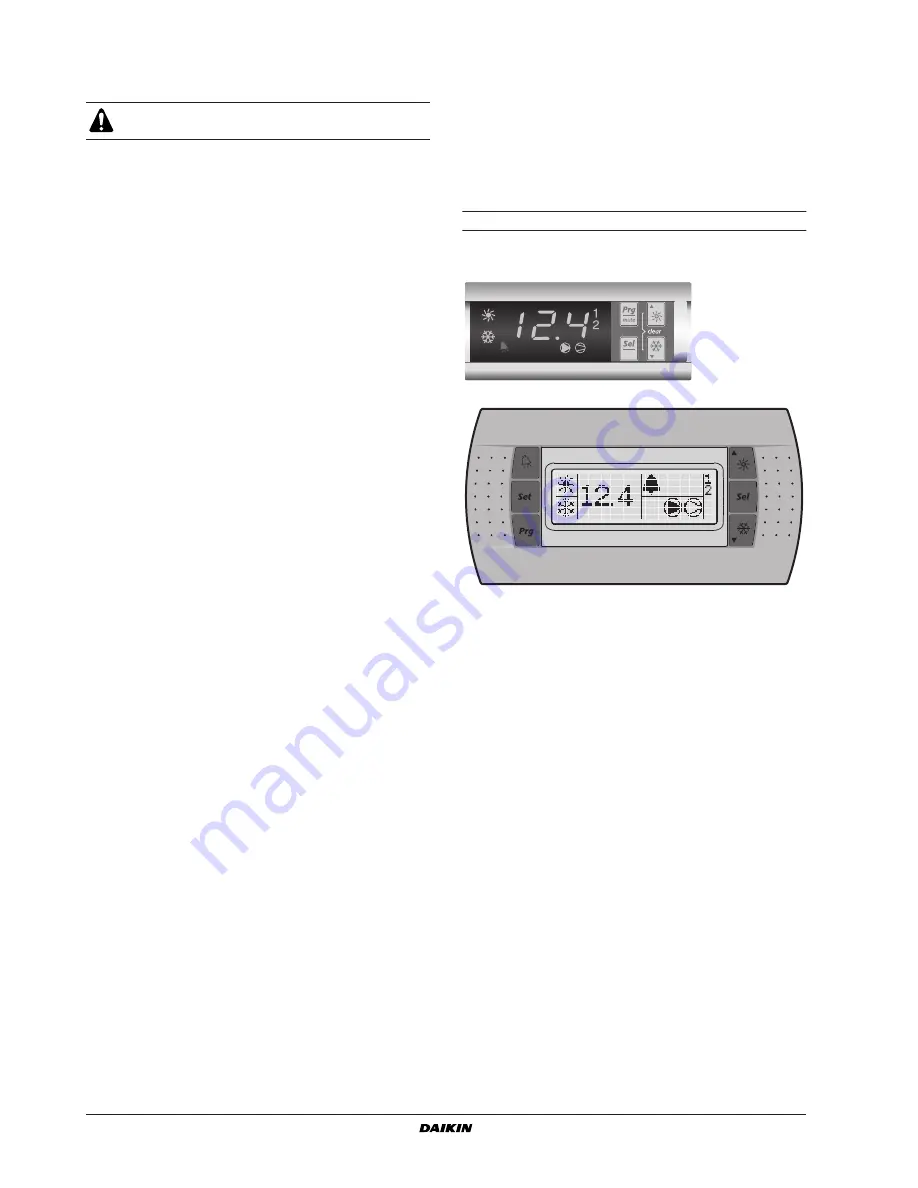
The digital controller consists of a numeric display, four labelled keys
which you can press and LEDs providing extra user information.

Figure - 

Digital controller

Figure - 

Remote user interface (optional kit)

Make sure that the circuit breaker on the power supply
panel of the unit is switched off.

Summary of Contents for EWWP014KBW1N

Page 1: ...OPERATION MANUAL EWWP014KBW1N EWWP022KBW1N EWWP028KBW1N EWWP035KBW1N EWWP045KBW1N EWWP055KBW1N EWWP065KBW1N Packaged water cooled water chillers...

Page 2: ...1 EWWP014KBW1N EWWP045KBW1N EWWP022KBW1N EWWP055KBW1N EWWP028KBW1N EWWP065KBW1N EWWP035KBW1N Packaged water cooled water chillers Operation manual READ THIS MANUAL ATTENTIVELY BEFORE STARTING UP THE U...

Page 3: ...led Model EWWP 045 055 065 Power supply Phase 3N Frequency Hz 50 Voltage V 400 Voltage tolerance 10 Recommended fuses aM 3x 40 3x 50 3x 50 Compressor Phase 3 Frequency Hz 50 Voltage V 400 Nominal runn...

Page 4: ...O PCB A2P input output The I O PCB A2P contains a reverse phase protector The reverse phase protector detects if the 3 phases of the power supply are connected correctly If a phase is not connected o...

Page 5: ...t from the water to prevent damage to the unit or blockage of the evaporator or condenser The water lter should be cleaned on a regular base Air purge valve delivered with the unit installed in the el...

Page 6: ...your local dealer 9 Power supply voltage Check the power supply voltage on the local supply panel The voltage should correspond to the voltage on the identi cation label of the unit Water supply Fill...

Page 7: ...n page 8 Resetting alarms on page 8 Resetting warnings on page 8 Keys digital controller Keys remote interface Main display Sensor readout menu Parameter selection menu Parameter setting menu A T Pres...

Page 8: ...the setting of the selected parameter Only valid for read write parameters 7 Press the B key to con rm the modi ed setting OR Press the A key to cancel the modi ed setting 8 Press the A key to return...

Page 9: ...ror communication failure between the digital controller of the unit and the remote user interface Con rm the correct selection of parameter code h23 This should be default setting 0 and con rm the co...

Page 10: ...hreshold for maintenance warning c10 and c11 0 0 100 x100 hours R W U 241 I c15 Total running hours of pump x100 hours R D 126 A d No user or direct parameters accessible f No user or direct parameter...

Page 11: ...ss the A key to cancel the modi ed setting 11 Press the A key to return to the parameter group 12 Press 2 times the A key to return to the main display If during the procedure no buttons are pressed f...

Page 12: ...te on off switch installed by the customer allows the user to switch the unit on without using the D or C key on the controller When user parameter h07 is set to 0 not active the unit can only be swit...

Page 13: ...able with read only status the command will not be executed at all Variables requested by the supervisory system that are not available in a chiller with an address card are sent from the address card...

Page 14: ...s a user parameter refer to How to consult and modify the user parameters on page 10 Variables database The BMS or supervisory system and the chiller unit communicate through a xed set of variables al...

Page 15: ...s activated Refer to the explanation of the digital controller in the chapter Resetting alarms on page 8 The remote ON OFF input is enabled and the remote switch is off Put the remote switch on or dis...

Page 16: ...e electrical components are not damaged or loose Earth connection Make sure that the earth wires are still connected properly and that the earth terminals are tightened Refrigerant circuit Check for l...

Page 17: ...ect parameter setting values s p or levels l p a a l p function is not used Select parameter group Select parameter Read and modify parameter D C 2 D C 2 2 C B A A C D B C D C D C D C D C D C D C D C...

Page 18: ......

Page 19: ......

Page 20: ...4PW61660 1A 2012 04 Copyright 2010 Daikin...

Reviews: