


D – 508 C – 07/02 D – EN pag. 18/36
Relief Valves
As a safety precaution and to meet code requirements, each chiller is equipped with pressure relief valves
located on the condenser coil, evaporator, heat recovery condenser (if supplied) and liquid receiver, for the
purpose of releasing excessive refrigerant pressure (caused by equipment malfunctioning, fire etc.) to the
atmosphere.
Oil Heater
The oil separator is equipped with an immersion electric heater that is installed in a tube and can be
removed without disturbing the oil or opening the refrigerant circuit.
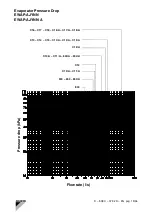
Evaporator water flow and pressure drop
Adjust the chilled water flow through the evaporator. The flow rates must remain between the minimum and
maximum values. Flow rates below the minimum values shown will result in laminar flow that will reduce efficiency,
cause erratic operation of the electronic expansion valve and could cause low temperature cut-out. On the other
hand flow rates exceeding the maximum values shown may cause erosion, vibration and possible breakage of
evaporator water connections and tubes. Measure the chilled water pressure drop across the evaporator at field
installed pressure taps. It is important not to include any pressure drop due to valves or strainers in the
measurement. Variable chilled water flow through the evaporator while the compressors are operating is not
recommended. Set points are valid for a constant flow and a variable temperature.
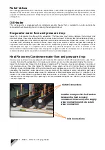
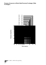
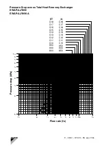
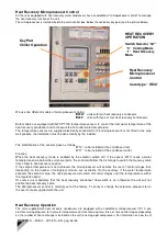
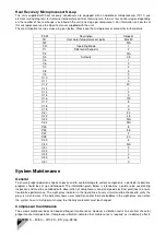
Heat Recovery Condenser water flow and pressure drop
Heat recovery condensers are supplied without the connection headers for both inlet and outlet water sides. These
headers, including the well pockets for microprocessor control sensors, must be provided locally by the installer.
Adjust the hot water flow through the heat recovery condenser. The flow rates must remain between the minimum
and maximum values. Flow rates below the minimum values shown will result in laminar flow that will reduce
efficiency, cause erratic operation of the unit and could cause high pressure cut-out. On the other hand, flow rates
exceeding the maximum values shown can cause erosion on the condenser water connections and tubes.
Measure the hot water pressure drop across the condenser at field installed pressure taps. It is important not to
include in the measurement any pressure drop due to valves or strainers. Variable hot water flow through the
condenser while the compressors are operating is not recommended. Set points are valid for a constant flow and a
variable temperature.
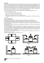
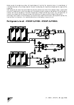
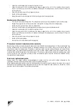
Outlet Connections
Inlet Connections
Installer must provide the Headers
between the heat recovery
condenser to have only one supply
water connection and one return
water connection