background image


D – 508 C – 07/02 D – EN  pag. 7/36 


Acoustic protection 

When the noise level must meet special requirements, it will be necessary to pay the maximum attention to ensure 
perfect insulation of the unit from the support base by applying appropriate vibration-dampening devices, applying 
vibration-dampening mounts on the water pipes and on the electrical connections. 


Water piping 

Due to the variety of piping practices, it is advisable to follow the recommendations of local authorities. They can 
supply the installer with the proper building and safety codes required for a safe and proper installation. 
Basically,  the  piping  should  be  designed  with  a  minimum  number  of  bends  and  changes  in  elevation  to  keep 
system cost down and performance up. It should contain: 

1.  Vibration eliminators to reduce vibration and noise transmission to the building. 

2.  Shutoff valves to isolate the unit from the piping system during unit servicing. 

3.  Manual  or  automatic  air  vent  valves  at  the  higher  points  of  the  system.  Drains  at  the  lower  points  of  the 

system. The evaporator and heat recovery condensers should not be the highest point in the piping system. 

4.  Devices to maintain adequate system water pressure (e.g. expansion tank or regulating valve). 

5.  Water temperature and pressure indicators located at the unit to aid in unit servicing. 

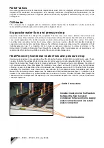
6.  A strainer or devices to remove foreign matter from the water before it enters the pump. The strainer should 

be  placed  far  enough  upstream  to  prevent  cavitations  at  the  pump  inlet  (consult  pump  manufacturer  for 
recommendations). The use of a strainer will prolong pump life and help maintain high system performance 
levels. 

7.  A strainer should be placed in the supply water line just prior to the inlet of the evaporator and heat recovery 

condensers. This will aid in preventing foreign material from entering and decreasing the performance of the 
heat exchangers. 

8.  The shell-and-tube evaporator has a thermostat and an  electric heater to prevent freeze-up down to -28°C. 

Any water piping to the unit must be protected to prevent freezing. 

9.  The shell-and-tube heat recovery condensers must be empty of water during the winter season, unless you fill 

the water circuit with ethylene glycol. 

10.  If  the  unit  is  used  as  a  replacement  chiller  on  a  previously  existing  piping  system,  the  system  should  be 

thoroughly  flushed  prior  to  unit  installation  and  then  regular  chilled  water  analysis  and  chemical  water 
treatment is recommended immediately at equipment start-up. 

11.  In the event glycol is added to the water system, as an afterthought for freeze protection, recognize that the 

refrigerant  suction  pressure  will  be  lower,  cooling  performance  less,  and  water  side  pressure  drop  greater. 
System safety devices such as freeze protection and low pressure protection must be reset. 

 
Prior to insulating the piping and filling the system, a preliminary leak check should be made. 


Evaporator/Heat Recovery condenser freeze protection 

All evaporators are equipped with a thermostatically controlled electric heater that provides freeze protection down 
to  -28°C.  However,  this  should  not  be  the  only  method  of  freeze  protection.  Unless  the  evaporator  and  heat 
recovery condensers are flushed and drained as is described below in note 4, two or more of the remaining three 
recommendations must be followed as part of the system design: 

1.  Continuous circulation of water through the piping and the heat exchanger. 

2.  Filling of glycol solution in the chilled water circuit. 

3.  Additional insulation and heating of the exposed piping. 

4.  Draining and flushing the chiller vessel with air during winter season. 

It  is  the  responsibility  of  the  installing  contractor  and/or  on-site  maintenance  personnel  to  ensure  that  this 
additional  protection  is  provided.  Routine  checks  should  be  made  to  ensure  adequate  freeze  protection  is 
maintained. 
Failure to do so may result in damage to unit components. Freeze damage is not considered a warranty failure. 
 

Summary of Contents for EWAP800AJYNN

Page 1: ...D 508 C 07 02 D EN pag 1 36 Air cooled screw chillers EWAP 800 C18AJYNN EWAP 850 C18AJYNN A 50Hz Refrigerant R 407C Installation Operation and Maintenance Manual D 508 C 07 02 D EN...

Page 2: ...D 508 C 07 02 D EN pag 2 36...

Page 3: ...ithout causing any damage to the chiller or injuries to qualified personnel Nomenclature EWA P 600 AJ YN N A Machine type ERA Air cooled condensing unit EWW Water cooled packaged water chiller EWL Rem...

Page 4: ...nced personnel with specific training in refrigeration must carry out servicing and maintenance of the unit Regular checking of safety devices should be carried out but routine maintenance should be c...

Page 5: ...tional lifting rings are on the same side of the control panel therefore the chiller has to be loaded into the container with the control panel on the container doors side Handling and lifting Care sh...

Page 6: ...ed Fit a water filter on the water inlet pipes Space requirements Since these units are air cooled it is important to ensure sufficient airflow across the condenser coils Two conditions must be avoide...

Page 7: ...exchangers 8 The shell and tube evaporator has a thermostat and an electric heater to prevent freeze up down to 28 C Any water piping to the unit must be protected to prevent freezing 9 The shell and...

Page 8: ...e 1 C 42 38 Min ambient temperature C 10 2 10 2 Max leaving evaporator water temperature C 10 10 Min leaving evap water temp without glycol C 4 4 Min leaving evap water temp with glycol C 8 8 Max evap...

Page 9: ...ight mm 2520 2520 2520 2520 2520 2520 Unit size C13 C14 C15 C16 C17 C18 Cooling capacity 1 kW 1284 2 1353 5 1426 3 1516 3 1583 0 1649 8 Power input 1 kW 509 1 537 9 564 5 604 3 636 8 669 4 COP 2 52 2...

Page 10: ...3 864 1012 1070 1122 1173 Max compressor current 3 A 950 1002 1064 1134 1193 1251 Fans current A 76 80 88 88 92 96 Max unit current 3 A 1026 1082 1152 1222 1285 1347 Max unit inrush current 4 A 1248 1...

Page 11: ...2230 Unit height mm 2520 2520 2520 2520 2520 2520 Unit size C13 C14 C15 C16 C17 C18 Cooling capacity 1 kW 1205 8 1271 3 1346 1 1422 1 1484 7 1547 4 Power input 1 kW 563 5 594 2 618 5 666 7 703 2 739 7...

Page 12: ...rrent 2 A 902 947 1053 1125 1182 1238 Max compressor current 3 A 978 1040 1069 1147 1207 1266 Fans current A 44 46 51 51 53 55 Max unit current 3 A 1022 1086 1120 1198 1260 1316 Max unit inrush curren...

Page 13: ...14 C15 C16 C17 C18 Cooling capacity 1 kW 1357 1 1427 1 1497 1 1594 7 1644 4 1729 1 Power input 1 kW 461 9 490 7 519 3 555 2 598 4 617 8 COP 2 94 2 91 2 88 2 87 2 75 2 80 Single screw compressors N 3 3...

Page 14: ...1023 1078 1121 Max compressor current 3 A 948 1002 1056 1123 1184 1245 Fans current A 100 104 112 112 112 120 Max unit current 3 A 1048 1106 1168 1235 1296 1365 Max unit inrush current 4 A 1232 1332...

Page 15: ...e C13 C14 C15 C16 C17 2 C18 2 Cooling capacity 1 kW 1299 3 1365 6 1435 8 1522 5 1586 0 1649 3 Power input 1 kW 499 0 529 9 558 2 600 3 635 0 669 6 COP 2 60 2 58 2 57 2 54 2 50 2 46 Single screw compre...

Page 16: ...rrent 2 A 809 852 979 1041 1107 1146 Max compressor current 3 A 948 1003 1053 1127 1189 1251 Fans current A 58 60 64 64 67 69 Max unit current 3 A 1006 1063 1117 1191 1256 1320 Max unit inrush current...

Page 17: ...52 5 76 0 C11 C11 76 0 73 0 76 0 72 5 71 0 69 0 60 0 53 0 76 0 C12 C12 77 0 73 5 76 5 73 0 71 5 69 0 60 5 53 5 76 5 C13 C13 77 5 73 0 76 0 73 0 71 5 69 0 60 5 53 0 76 0 C14 C14 77 5 73 5 75 5 73 5 71...

Page 18: ...in the measurement Variable chilled water flow through the evaporator while the compressors are operating is not recommended Set points are valid for a constant flow and a variable temperature Heat R...

Page 19: ...N pag 19 36 Evaporator Pressure Drop EWAP AJYNN EWAP AJYNN A Pressure drop kPa Flow rate l s C16 C17 C18 C16 A C17 A C18 A C13 C14 C15 C13 A C14 A C15 A C12 A C10 A C11 A 900 A 950 A C12 C10 A C11 A 9...

Page 20: ...EN pag 20 36 Pressure Drop across Partial Heat Recovery Exchanger Plate Exchanger ST C18 C17 C16 C15 C14 C13 C12 C11 C10 950 900 800 A C18 C17 C16 C15 C14 C13 C12 C11 C10 950 900 850 Flow rate l s Pr...

Page 21: ...re Drop across Total Heat Recovery Exchanger EWAP AJYNN EWAP AJYNN A 0 1 2 3 4 5 6 0 1 2 3 4 5 6 6 798 ST C18 C17 C16 C15 C14 C13 C12 C11 C10 950 900 800 A C18 C17 C16 C15 C14 C13 C12 C11 C10 950 900...

Page 22: ...tarting operating or shutting it down During the initial start up of the chiller the DAIKIN technician will be available to answer any questions and advise procedures for a correct operation It is rec...

Page 23: ...ode in order to compensate for the different volume refrigerant side between the coil condenser and the heat recovery condenser The liquid refrigerant goes through the filter dryer where any existing...

Page 24: ...ed to work in partial failure condition thanks to the distributed multiprocessor logic system Full operational routines for following conditions High ambient temperature High thermal load High evapora...

Page 25: ...supervisory systems The controller can be monitored locally or via modem using the supervision program The supervisory system is the best solution To centralize all the information in just one local a...

Page 26: ...mperature value below the current setpoint the control will allow the first stage to switch the four way valve from chiller to heat recovery position If the setpoint temperature is not achieved the mi...

Page 27: ...covery condenser to the condenser coil while also switching on the respective fan motors 6 In case of lack of water in the heat recovery condenser the unit is automatically put in cooling mode only St...

Page 28: ...30 C22 43 C23 N A C24 N A P25 8 P26 55 P27 2 P28 20 C29 4 C30 N A C31 0 C32 1 C33 0 C50 4 C51 0 System Maintenance General To ensure proper operation at peak capacity and to avoid damage to system com...

Page 29: ...a restriction elsewhere in the liquid line If sub cooling is low add refrigerant to make the sight glass clear If sub cooling is normal and flashing is visible in the sight glass replace the filter dr...

Page 30: ...supplied with IP54 protection as standard Insulation class F they are protected against overloading and short circuits by circuit breakers located inside the electrical control panel Air cooled conden...

Page 31: ...to carefully clean the system before attempting the vacuum operation by using the filter dryer clean out method which basically involves the use of special filter dryers including a suitable desiccant...

Page 32: ...d indicates the same temperature as the local thermometer or the discrepancy does not exceed 0 1 C Verify that the flow switch es is are connected to the electrical panel at the terminal blocks M3 8 M...

Page 33: ...shut off valves of the refrigerant circuits Switch off the water pumps Service the unit in accordance with the program Procedure to return materials under warranty Material may not be returned except...

Page 34: ...o unit for correct phasing Check voltage 8 Overloads are reset manually Reset overload button Clear alarm on Microprocessor 9 Check wiring Repair or replace contactor 10 Determine type and cause of sh...

Page 35: ...rator dirty 3 Clogged liquid line filter drier 4 Expansion valve malfunctioning 5 Insufficient water flow to evaporator 6 Water temperature leaving evaporator is too low 7 Evaporator head ring gasket...

Page 36: ...oled screw chillers EWAP 800 C18AJYNN EWAP 850 C18AJYNN A Zandvoordestraat 300 B 8400 Ostend Belgium www daikineurope com Daikin Europe N V is participating in the EUROVENT Certification Programme Pro...

Reviews: