background image

7 Configuration

Installation manual

22

ETVH/23E

Daikin Altherma 3 H HT F

4P644728-1B – 2022.03

5

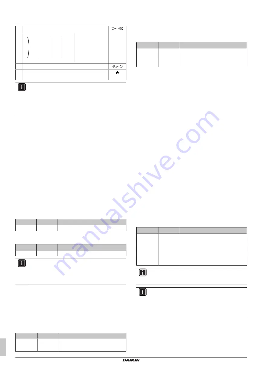
Turn the right dial to modify the value from 15 to 20.

00
01

20

02
03
04

05
06
07
08
09

0A
0B
0C
0D
0E

1

6

Press the left dial to confirm the new setting.

7

Press the center button to go back to the home
screen.

INFORMATION

When  you  change  the  overview  settings  and  you  go  back
to  the  home  screen,  the  user  interface  will  show  a  popup
screen and request to restart the system.

When  confirmed,  the  system  will  restart  and  recent
changes will be applied.

7.2

Configuration wizard

After  first  power  ON  of  the  system,  the  user  interface  starts  a
configuration wizard. Use this wizard to set the most important initial
settings  for  the  unit  to  run  properly.  If  required,  you  can  afterwards
configure  more  settings.  You  can  change  all  these  settings  via  the
menu structure.

Protective functions

The unit is equipped with the following protective functions:

▪ Room antifrost [2-06]

▪ Water pipe freeze prevention [4-04]

▪ Tank disinfection [2-01]

The unit automatically runs the protective functions when necessary.
During installation or service, this behaviour is undesired. Therefore,
the  protective  functions  can  be  disabled.  For  more  information,  see
the Installer reference guide, chapter Configuration.

7.2.1

Configuration wizard: Language

#

Code

Description

[7.1]

N/A

Language

7.2.2

Configuration wizard: Time and date

#

Code

Description

[7.2]

N/A

Set the local time and date

INFORMATION

By  default,  daylight  savings  time  is  enabled  and  clock
format  is  set  to  24  hours.  If  you  want  to  change  these
settings,  you  can  do  this  in  the  menu  structure  (

User

settings

 > 

Time/date

) once the unit is initialised.

7.2.3

Configuration wizard: System

Indoor unit type

The indoor unit type is displayed, but cannot be adjusted.

Backup heater type

The  backup  heater  is  adapted  to  be  connected  to  most  common
European electricity grids. The type of backup heater can be viewed
but not changed.

#

Code

Description

[9.3.1]

[E‑03]

▪ 3: 

6V

▪ 4: 

9W

Domestic hot water

The following setting determines if the system can prepare domestic
hot water or not, and which tank is used. This setting is read only.

#

Code

Description

[9.2.1]

[E‑05]

(a)

[E‑06]

(a)

[E‑07]

(a)

Integrated

The  backup  heater  will  also  be  used
for domestic hot water heating.

(a)

Use the menu structure instead of the overview settings. Menu
structure setting [9.2.1] replaces the following 3 overview settings:
• [E-05]: Can the system prepare domestic hot water?
• [E-06]: Is a domestic hot water tank installed in the system?
• [E-07]: What kind of domestic hot water tank is installed?

Emergency

When  the  heat  pump  fails  to  operate,  the  backup  heater  can  serve
as  an  emergency  heater.  It  then  takes  over  the  heat  load  either
automatically or by manual interaction.

▪ When 

Emergency

  is  set  to 

Automatic

  and  a  heat  pump  failure

occurs,  the  backup  heater  automatically  takes  over  the  domestic
hot water production and space heating.

▪ When 

Emergency

  is  set  to 

Manual

  and  a  heat  pump  failure

occurs, the domestic hot water heating and space heating stops.

To  manually  recover  it  via  the  user  interface,  go  to  the

Malfunctioning

  main  menu  screen  and  confirm  whether  the

backup heater can take over the heat load or not.

▪ Alternatively, when 

Emergency

 is set to:

auto  SH  reduced/DHW  on

,  space  heating  is  reduced  but

domestic hot water is still available.

auto  SH  reduced/DHW  off

,  space  heating  is  reduced  and

domestic hot water is NOT available.

auto  SH  normal/DHW  off

,  space  heating  operates  as

normally but domestic hot water is NOT available.

Similarly  as  in 

Manual

  mode,  the  unit  can  take  the  full  load  with

the  backup  heater  if  the  user  activates  this  via  the

Malfunctioning

 main menu screen.

To keep energy consumption low, we recommend to set 

Emergency

to 

auto SH reduced/DHW off

 if the house is unattended for longer

periods.

#

Code

Description

[9.5.1]

[4-06]

▪ 0: 

Manual

▪ 1: 

Automatic

▪ 2: 

auto SH reduced/DHW on

▪ 3: 

auto SH reduced/DHW off

▪ 4: 

auto SH normal/DHW off

INFORMATION

The  auto  emergency  setting  can  be  set  in  the  menu
structure of the user interface only.

INFORMATION

If  a  heat  pump  failure  occurs  and 

Emergency

  is  set  to

Manual

,  the  room  frost  protection  function,  the  underfloor

heating  screed  dryout  function,  and  the  water  pipe
antifreeze function will remain active even if the user does
NOT confirm emergency operation.

Number of zones

The  system  can  supply  leaving  water  to  up  to  2  water  temperature
zones. During configuration, the number of water zones must be set.

Summary of Contents for ETVX16E9W7

Page 1: ...therma 3 H HT F English Installation manual Daikin Altherma 3 H HT F ETVH16S18E 6V ETVH16S23E 6V ETVH16S18E 9W ETVH16S23E 9W ETVX16S18E 6V ETVX16S23E 6V ETVX16S18E 9W ETVX16S23E 9W A B C Z 1 2 3 9 htt...

Page 2: ...m rnicemi nebo p edpisy za p edpokladu e tyto v robky jsou pou v ny v souladu s na imi pokyny u skladu sa sljede om direktivom ma ili odredbom a uz uvjet da se proizvodi koriste sukladno na im uputama...

Page 3: ...te 22 7 2 3 Configuration wizard System 22 7 2 4 Configuration wizard Backup heater 23 7 2 5 Configuration wizard Main zone 24 7 2 6 Configuration wizard Additional zone 25 7 2 7 Configuration wizard...

Page 4: ...the instructions from this manual See 5 Piping installation 48 In case of freeze protection by glycol WARNING Ethylene glycol is toxic WARNING Due to the presence of glycol corrosion of the system is...

Page 5: ...isible 4 Unit installation 4 1 Preparing the installation site 4 1 1 Installation site requirements of the indoor unit The indoor unit is designed for indoor installation only and for the following am...

Page 6: ...lowing cases 4 2 2 To lower the switch box on the indoor unit 46 4 3 2 To connect the drain hose to the drain 47 When you need access to the high voltage switch box 2 T25 5 If you need access to the h...

Page 7: ...hose to the drain See 4 3 2 To connect the drain hose to the drain 47 3 Slide the indoor unit into position 4 Adjust the height of the leveling feet to compensate for floor irregularities The maximum...

Page 8: ...er volume and flow rate Minimum water volume Check that the total water volume in the installation is minimum 20 litres the internal water volume of the outdoor unit NOT included NOTICE When circulati...

Page 9: ...e field supplied NOTICE Overpressure bypass valve delivered as accessory We recommend to install the overpressure bypass valve in the space heating water circuit Mind the minimum water volume when cho...

Page 10: ...n is then lower than assumed As a result the hydraulic components might freeze up after all Take preventive actions to ensure a minimal exposure of the glycol to air Types of glycol The types of glyco...

Page 11: ...TICE The distance between the high voltage and low voltage cables should be at least 50 mm 6 1 About electrical compliance Only for the backup heater of the indoor unit See 6 3 2 To connect the backup...

Page 12: ...1 6 Room sensor offset Item Description WLAN module See Installation manual of the WLAN module Addendum book for optional equipment Installer reference guide Use the cable delivered with the WLAN modu...

Page 13: ...9 S1S N L 5 6 1N 50 Hz 230 V AC 6 3 A 1 2 3 a b c B A B 5 6 1 2 3 X2M X1A X11YA X11YB X11Y X5M 9 10 X1M a b c a Interconnection cable main power supply b Normal kWh rate power supply c Preferential po...

Page 14: ...ng the limits for voltage changes voltage fluctuations and flicker in public low voltage supply systems for equipment with rated current 75 A provided that the system impedance Zsys is less than or eq...

Page 15: ...valve and a NO normally open valve A M2S B A B 21 28 X2M B 21 29 X2M NO NC 3 Fix the cable with cable ties to the cable tie mountings 6 3 4 To connect the electricity meters Wires 2 per meter 0 75 mm...

Page 16: ...A4P 1 2 Wires connected to the alarm output 3 Wire between X2M and A4P A4P Installation of EKRP1HBAA is required A Y1 7 B A B 7 9 X2M A4P Y1 YC X1M a b a Installation of EKRP1HBAA is required b Prewi...

Page 17: ...1 Open the following see 4 2 1 To open the indoor unit 45 1 Top panel 1 2 3 2 User interface panel 3 Upper switch box cover 2 Connect the changeover to external heat source cable to the appropriate t...

Page 18: ...le with cable ties to the cable tie mountings NOTICE Make sure to select and install the safety thermostat according to the applicable legislation In any case to prevent unnecessary tripping of the sa...

Page 19: ...10 X5M 9 S10S X5M 6 X5M 5 S11S 2 1 B A B X5M 3 4 5 6 9 10 1314 3 Fix the cables with cable ties to the cable tie mountings In case of high voltage Smart Grid contacts Wires Smart Grid pulse meter 0 5...

Page 20: ...essary bundle excessive cable length with a cable tie 6 3 12 To connect the WLAN cartridge delivered as accessory D Wireless gateway 1 Insert the WLAN cartridge into the cartridge slot on the user int...

Page 21: ...a the breadcrumb in the home menu screen or the menu structure To enable breadcrumbs press the button in the home screen For example 2 9 Accessing settings via the code in the overview field settings...

Page 22: ...This setting is read only Code Description 9 2 1 E 05 a E 06 a E 07 a Integrated The backup heater will also be used for domestic hot water heating a Use the menu structure instead of the overview set...

Page 23: ...aller the possibility to indicate whether the system is filled with glycol or water This is important in case glycol is used to protect the water circuit against freezing If NOT set correctly the liqu...

Page 24: ...g 0 Underfloor heating Maximum 55 C Variable 1 Fancoil unit Maximum 55 C Variable 2 Radiator Maximum 70 C Fixed 10 C NOTICE Average emitter temperature Leaving water temperature Delta T 2 This means t...

Page 25: ...acts upon it Code Description 5 6 6 0D Heat up mode 0 Reheat only Only reheat operation is allowed 1 Schedule reheat The domestic hot water tank is heated according to a schedule and between the sched...

Page 26: ...as climate and the insulation of the building the curve can be adjusted by an installer or user Types of weather dependent curve There are 2 types of weather dependent curves 2 points curve Slope off...

Page 27: ...oint mode to Main zone Heating 2 4 Main zone Setpoint mode WD heating fixed cooling OR Weather dependent Main zone Cooling 2 4 Main zone Setpoint mode Weather dependent Additional zone Heating 3 4 Add...

Page 28: ...tat type Only applicable in external room thermostat control NOTICE If an external room thermostat is used the external room thermostat will control the room frost protection However the room frost pr...

Page 29: ...rical heaters Limit setting kW Enable room buffering Allow heater Allow pump 9 Installer settings Configuration wizard Domestic hot water Backup heater Emergency Balancing Water pipe freeze prevention...

Page 30: ...ld wiring has been carried out according to this document and the applicable legislation Between the local supply panel and the outdoor unit Between indoor unit and outdoor unit Between the local supp...

Page 31: ...e temperatures 1 In the menu go to Sensors 2 Select the temperature information 8 2 4 To perform an actuator test run Purpose Perform an actuator test run to confirm the operation of the different act...

Page 32: ...sult in cracking of the screed NOTICE For the underfloor heating screed dryout to be able to start make sure the following settings are met 4 00 1 C 02 0 D 01 0 4 08 0 4 01 1 9 Hand over to the user O...

Page 33: ...ing cooling Water IN screw connection 1 a2 Space heating cooling Water OUT screw connection 1 b1 DHW Cold water IN screw connection 3 4 b2 DHW Hot water OUT screw connection 3 4 c1 Water IN from outdo...

Page 34: ...rnal thermistor Heat pump convector Heat pump convector Add LWT Additional leaving water temperature On OFF thermostat wired ON OFF thermostat wired On OFF thermostat wireless ON OFF thermostat wirele...

Page 35: ...rical meters For HV smartgrid For high voltage Smart Grid For LV smartgrid For low voltage Smart Grid For safety thermostat For safety thermostat For smartgrid For Smart Grid Inrush Inrush current Max...

Page 36: ...ired room thermostat 5 core for C H operation 4 core for H only operation 3 core for C H operation 2 core for H only operation communication 2 core OPTIONAL PART External room thermostat Heat pump con...

Page 37: ......

Page 38: ......

Page 39: ......

Page 40: ...4P644728 1B 2022 03 Copyright 2021 Daikin 4P644728 1 B 00000002 Verantwortung f r Energie und Umwelt...

Reviews: