background image

3

Design Temperature

Suggested  Minimum  Elevation

+15° and above

2 1/2"

-5° to +14°

8"

below -5°

12"

S

AFE

 R

EFRIGERANT

 H

ANDLING

While these items will not cover every conceivable situation, they
should serve as a useful guide.

T

O


AVOID


POSSIBLE


INJURY

EXPLOSION


OR


DEATH

PRACTICE


SAFE


HANDLING


OF


REFRIGERANTS

.

WARNING

R

EFRIGERANTS


ARE


HEAVIER


THAN


AIR

. T

HEY


CAN

 “

PUSH


OUT

” 

THE


OXYGEN


IN


YOUR


LUNGS


OR


IN


ANY


ENCLOSED


SPACE

. T

O


AVOID


POSSIBLE


DIFFICULTY


IN


BREATHING


OR


DEATH

:

• N

EVER


PURGE


REFRIGERANT


INTO


AN


ENCLOSED


ROOM


OR


SPACE

. B

Y


LAW

ALL


REFRIGERANTS


MUST


BE


RECLAIMED

.

• I

F


AN


INDOOR


LEAK


IS


SUSPECTED

THOROUGHLY


VENTILATE


THE


AREA


BEFORE


BEGINNING


WORK

.

• L

IQUID


REFRIGERANT


CAN


BE


VERY


COLD

. T

O


AVOID


POSSIBLE


FROST


BITE


OR


BLINDNESS

AVOID


CONTACT


AND


WEAR


GLOVES


AND


GOGGLES

. I

F


LIQUID


REFRIGERANT


DOES


CONTACT


YOUR


SKIN


OR


EYES

SEEK


MEDICAL


HELP


IMMEDIATELY

.

• A

LWAYS


FOLLOW

 EPA 

REGULATIONS

. N

EVER


BURN


REFRIGERANT

AS


    P

OISONOUS


GAS


WILL


BE


PRODUCED

.

WARNING

T

O


AVOID


POSSIBLE


EXPLOSION

:

• N

EVER


APPLY


FLAME


OR


STEAM


TO


A


REFRIGERANT


CYLINDER

. I

F


YOU


MUST


HEAT


A


CYLINDER


FOR


FASTER


CHARGING

PARTIALLY


IMMERSE


IT


IN


WARM


WATER

.

• N

EVER


FILL


A


CYLINDER


MORE


THAN

 80% 

FULL


OF


LIQUID


REFRIGERANT

.

• N

EVER


ADD


ANYTHING


OTHER


THAN

 R-22 

TO


AN

 R-22 

CYLINDER


OR

 R-

   410A 

TO


AN

 R-410A 

CYLINDER

. T

HE


SERVICE


EQUIPMENT


USED


MUST


BE


LISTED


OR


CERTIFIED


FOR


THE


TYPE


OF


REFRIGERANT


USED

.

• S

TORE


CYLINDERS


IN


A


COOL

DRY


PLACE

. N

EVER


USE


A


CYLINDER


AS


A


   P

LATFORM


OR


A


ROLLER

.

WARNING

T

O


AVOID


POSSIBLE


EXPLOSION

USE


ONLY


RETURNABLE

 (

NOT


DISPOSABLE

SERVICE


CYLINDERS


WHEN


REMOVING


REFRIGERANT


FROM


A


SYSTEM

.

• E

NSURE


THE


CYLINDER


IS


FREE


OF


DAMAGE


WHICH


COULD


LEAD


TO


A


LEAK


OR


EXPLOSION

.

• E

NSURE


THE


HYDROSTATIC


TEST


DATE


DOES


NOT


EXCEED

 5 

YEARS

.

• E

NSURE


THE


PRESSURE


RATING


MEETS


OR


EXCEEDS

 400 

PSIG

.

W

HEN


IN


DOUBT

DO


NOT


USE


CYLINDER

.

WARNING

R

EFRIGERANT

 L

INES

T

HE


COMPRESSOR

 POE 

OIL


FOR

 R-410A 

UNITS


IS


EXTREMELY


SUSCEPTIBLE


TO


MOISTURE


ABSORPTION


AND


COULD


CAUSE


COMPRESSOR


FAILURE

. D

O


NOT


LEAVE


SYSTEM


OPEN


TO


ATMOSPHERE


ANY


LONGER


THAN


NECESSARY


FOR


INSTALLATION

.

CAUTION

Use only refrigerant grade (dehydrated and sealed) copper tubing
to connect the condensing unit with the indoor evaporator.  After
cutting the tubing, install plugs to keep refrigerant tubing clean
and dry prior to and during installation.  Tubing should always be
cut square keeping ends round and free from burrs.  Clean the
tubing to prevent contamination.

Do NOT let refrigerant lines come in direct contact with plumbing,
ductwork, floor joists, wall studs, floors, and walls.  When run-
ning refrigerant lines through a foundation or wall, openings
should allow for sound and vibration absorbing material to be
placed or installed between tubing and foundation. Any gap be-
tween foundation or wall and refrigerant lines should be filled
with a pliable silicon-based caulk, RTV or a vibration damping
material. Avoid suspending refrigerant tubing from joists and studs
with rigid wire or straps that would come in contact with the
tubing. Use an insulated or suspension type hanger. Keep both
lines separate and always insulate the suction line.

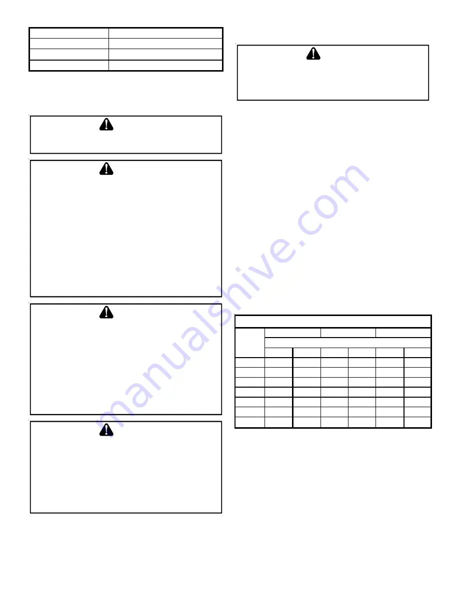
These sizes are suitable for line lengths of 79 feet or less. If a run
of more than eighty feet is required, refer to Remote Cooling Ser-
vice Manual, or TP-106 Long Line Set Application R-22, or TP-107
Long Line Set Application R-410A or contact your distributor for
assistance.

Cond

Unit

Tons

Suct

Liq

Suct

Liq

Suct

Liq

1 1/2

5/8

1/4

3/4

3/8

3/4

3/8

2

5/8

1/4

3/4

3/8

3/4

3/8

2 1/2

5/8

1/4

3/4

3/8

7/8

3/8

3

3/4

3/8

7/8

3/8

1 1/8

3/8

3 1/2

7/8

3/8

1 1/8

3/8

1  1/8

3/8

4

7/8

3/8

1 1/8

3/8

1 1/8

3/8

5

7/8

3/8

1 1/8

3/8

1 1/8

3/8

Line Diameter (In. OD)

RECOMMENDED INTERCONNECTING TUBING (Ft)

0-24

25-49

    50-79*

* Lines greater than 79 feet in length or vertical elevation changes more 
than 50 feet 

refer to  the Remote Cooling Service  Manual or contact your 

distributor for assistance.

Insulation is necessary to prevent condensation from forming
and dropping from the suction line.  Armaflex (or satisfactory
equivalent) with 3/8” min. wall thickness is recommended.  In
severe conditions (hot, high humidity areas) 1/2” insulation may
be required.  Insulation must be installed in a manner which
protects tubing from damage and contamination.

Where possible, drain as much residual compressor oil from ex-
isting systems, lines, and traps; pay close attention to low areas
where oil may collect.  

NOTE: 

If changing refrigerant types, ensure

the indoor coil and metering device is compatible with the type of
refrigerant being used; otherwise, the indoor coil must be replaced.

Summary of Contents for DZ16TC0241

Page 1: ...d units CODES REGULATIONS This product is designed and manufactured to comply with na tional codes Installation in accordance with such codes and or prevailing local codes regulations is the responsibility of the in staller The manufacturer assumes no responsibility for equip ment installed in violation of any codes or regulations Rated performance is achieved after 72 hours of operation Rated per...

Page 2: ...ions Either side adjacent the valves can be placed toward the structure provided the side away from the structure maintains minimum service clearance Corner in stallations are strongly discouraged OK OK AA AA A A C C C C OK OK OK OK NOT RECOMMENDED AA AA AA AA AA B B B B Model Type A B C AA Residential 10 10 18 20 Light Commercial 12 12 18 24 Minimum Airflow Clearance This unit can be located at g...

Page 3: ...utting the tubing install plugs to keep refrigerant tubing clean and dry prior to and during installation Tubing should always be cut square keeping ends round and free from burrs Clean the tubing to prevent contamination Do NOT let refrigerant lines come in direct contact with plumbing ductwork floor joists wall studs floors and walls When run ning refrigerant lines through a foundation or wall o...

Page 4: ...a blockage or failure of the metering device 3 After brazing quench the joints with water or a wet cloth to prevent overheating of the service valve 4 Ensure the filter drier paint finish is intact after brazing If the paint of the steel filter drier has been burned or chipped repaint or treat with a rust preventative This is especially important on suction line filter driers which are continually...

Page 5: ...AMAGE USE COPPER CONDUCTORS WARNING The condensing unit rating plate lists pertinent electrical data necessary for proper electrical service and overcurrent protec tion Wires should be sized to limit voltage drop to 2 max from the main breaker or fuse panel to the condensing unit Con sult the NEC CEC and all local codes to determine the correct wire gauge and length Local codes often require a dis...

Page 6: ...hecked using superheat when using a piston and subcooling when using TXV equipped indoor coil to verify proper charge Open the suction service valve first If the liquid service valve is opened first oil from the compressor may be drawn into the in door coil TXV restricting refrigerant flow and affecting operation of the system When opening valves with retainers open each valve only until the top o...

Page 7: ...ing guidelines and methods to check unit operation and ensure that the refrigerant charge is within limits Charge the unit on low stage 1 Purge gauge lines Connect service gauge manifold to base valve service ports Run system at least 10 minutes to allow pressure to stabilize 2 Temporarily install a thermometer on the liquid line at the liquid line service valve and 4 6 from the compressor on the ...

Page 8: ...ree times Refer to the fault code definitions at the end of this manual for more details 6 A forced defrost can be initiated by pressing TEST and RECALL push buttons simultaneously for more than 1 second with a valid call for heat The forced defrost can be terminated by A 10 minute lapse in time A coil temperature rise above 75 F or By pressing the two buttons again for more than 1 sec ond COMFORT...

Page 9: ...ay be removed wire connections made to the plug and replaced It is strongly recommended that you do not connect multiple wires into a single terminal Wire nuts are recommended to ensure one wire is used for each terminal Failure to do so may result in intermittent operation Typical 18 AWG thermostat wire may be used to wire the system components 150 feet is the maximum recommended length of wire b...

Page 10: ...wer supply to the air conditioner heat pump is continuously below 187 VAC The control will only store this fault the first three consecutive times the fault occurs NOTE It is highly recommended that the fault history be cleared after performing maintenance or servicing the heat pump IDENTIFICATION Model Number Serial Number and Software Version are displayed within this menu A model number check w...

Page 11: ...s and the corresponding potential problem Green receive LED Indicates network traffic The table below indicates the LED status and the corresponding potential problem LEARN button Used to reset the network Depress the button for approximately 2 seconds to reset the network SYSTEMTROUBLESHOOTING NOTE Refer to the instructions accompanying the CT compatible indoor air handler furnace modular blower ...

Page 12: ... blocks are securely twisted together prior to inserting into terminal block Verify heat pump installation type legacy traditional or communicating Check data 1 data 2 voltages Rapid Flashing Normal network traffic Control is talking on network as expected None None Data 1 and data 2 wires reversed at heat pump thermostat or CT compatible indoor unit Check communications wiring data 1 data 2 wires...

Page 13: ...Faulty Evap Fan Motor Repair or Replace Shorted or Grounded Fan Motor Test Motor Windings Improper Cooling Anticipator Check Resistance of Anticipator Shortage of Refrigerant Test For Leaks Add Refrigerant Restricted Liquid Line Remove Restriction Replace Restricted Part Open Element or Limit on Elec Heater Test Heater Element and Controls Dirty Air Filter Inspect Filter Clean or Replace Dirty Ind...

Page 14: ...ent part Air conditioner heat pump fails to operate Integrated control module diagnostic status LED display shows the indicated code BLANK b 0 Circulator blower motor is not running when it should be running Indoor bIower motor problem Communications error between indoor and outdoor unit Check indoor bIower motor Check indoor bIower motor wiring Check indoor unit control Repair replace any faulty ...

Page 15: ... to repair Use memory card for your specific model Insert memory card BEFORE turning power ON M emory card may be removed after data is loaded Turn power OFF before removing memory card Error code will be cleared once data is loaded Air conditioner heat pump fails to operate Air conditioner heat pump operating at reduced performance Air conditioner heat pump operating at low stage when e peeled to...

Page 16: ...Four consecutive compressor protector trips with average run time between trips greater than 3 hours Compressor operating at high speed and outdoor fan operating at low speed Integrated control module diagnostic status LED display shows the indicated code BLANK 0 1 Low Side Fault Low refrigerant charge Restriction in liquid line Indoor blower motor failure Indoor thermostat set extremely low Verif...

Page 17: ...motor capacitor replace as needed Turn power OFF prior to repair Fault will clear after 4 consecutive normal cycles Fault may be cleared by cycling 24 VAC to control Replace with correct replacement part s Compressor and outdoor fan are off Thermostat demand is present Intergrated control module diagnostic status LED display shows the indicated code BLANK 0 2 High Pressure Cut Out Trip Blocked con...

Page 18: ...r M ust clear fault by cycling 24V AC to control Replace with correct replacement part s Compressor and outdoor fun are off for greater than 4 hours Low pressure and high pressure switches are closed Integrated control module diagnostic status LED display shows the indicated code BLANK 0 5 Open Circuit Power is disconnected Failed compressor protector Compressor not properly wired to control Check...

Page 19: ...g 24 VAC to control Replace with correct replacement part s Compressor and outdoor fan are off Low pressure and high pressure switches are closed Open start circuit has been detected 4 times within 5 minute delay between each detection Integrated control module diagnostic status LED display shows the indicated code BLANK L 7 Open Run Circuit Lockout Compressor run winding is open Compressor not pr...

Page 20: ...acitor Faulty run capacitor wiring Check compressor repair replace as needed Check wiring repair replaced as needed Check run capacitor replace as needed Turn power OFF prior to repair Fault will clear after 1normal cycle M ust clear fault by cycling 24 VAC to control Replace with correct replacement part s Air conditioner heat pump may appear to be operating normally Compressor protecor may be op...

Page 21: ...irflow If cleaning of the outdoor coil becomes necessary hire a qualified servicer Inexperienced people could easily puncture the tubing in the coil Even a small hole in the tubing could eventually cause a large loss of refriger ant Loss of refrigerant can cause poor operation and or severe equipment damage Do not use a condensing unit cover to protect the outdoor unit during the winter unless you...

Page 22: ...22 THIS PAGE LEFT INTENTIONALLY BLANK ...

Page 23: ...23 THIS PAGE LEFT INTENTIONALLY BLANK ...

Page 24: ...24 Our continuing commitment to quality products may mean a change in specifications without notice 2013 2014 2016 2017 5151 San Felipe St Suite 500 Houston TX 77056 www daikincomfort com ...

Reviews: