41
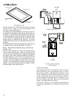
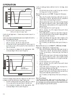
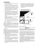
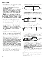
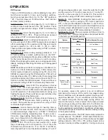
fan operation, the thermostat sends a fan request along
with the continuous fan demand to the furnace. The fur-
nace, in turn, sends the demand to the ECM motor. The
ECM motor delivers the requested continuous fan airflow.
F
OSSIL
F
UEL
A
PPLICATIONS
This furnace can be used in conjunction with a ComfortNet™
compatible heat pump in a fossil fuel application. A fossil fuel
application refers to a combined gas furnace and heat pump
installation which uses an outdoor temperature sensor to de-
termine the most cost efficient means of heating (heat pump
or gas furnace).
The balance point temperature may be ad-
justed via the CTK0* thermostat advanced user menus (see
CTK0* instructions for additional information).
CTK0* W
IRING
NOTE:
Refer to
Electrical Connections
for 115 volt line
connections to the furnace.
NOTE:
A removable plug connector is provided with the control
to make thermostat wire connections. This plug may be
removed, wire connections made to the plug, and replaced.
Multiple wires imust be twisted together prior to inserting into
the plug connector. Failure to do so may result in intermittent
operation.
Typical 18 AWG thermostat wire may be used to wire the sys-
tem components. One hundred (100) feet is the maximum
length of wire between indoor unit and outdoor unit, or be-
tween indoor unit and thermostat. Wire runs over (100) feet
require larger gauge wire.
F
OUR
-W
IRE
I
NDOOR
AND
O
UTDOOR
W
IRING
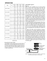
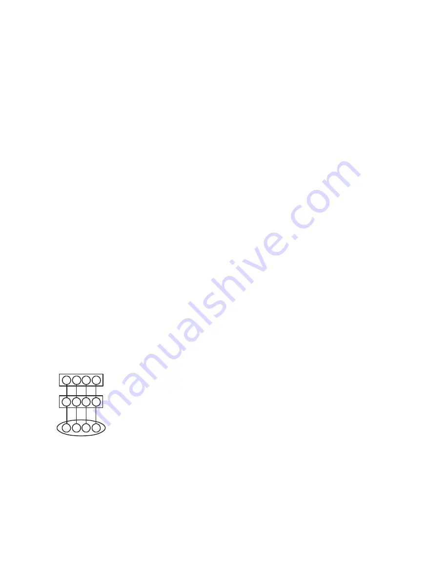
Typical ComfortNet wiring will consist of four wires between
the indoor unit and outdoor unit and between the indoor unit
and thermostat. The required wires are: (a) data lines, 1 and
2; (b) thermostat “R” (24 VAC hot) and “C” (24 VAC common).
1
2
R C
1
2
R C
CTK01 / 02
Thermostat
ComfortNet Compatible Furnace
Integrated Control Module
ComfortNet Compatible
Integrated Control Module Straight Cooling
1
2
R C
System Wiring using Four-Wires
T
WO
-W
IRE
O
UTDOOR
, F
OUR
-W
IRE
I
NDOOR
W
IRING
Two wires can be utilized between the indoor and outdoor units.
For this wiring scheme, only the data lines, 1 and 2, are needed
between the indoor and outdoor units. A 40VA, 208/230 VAC to
24VAC transformer must be installed in the outdoor unit to pro-
vide 24VAC power to the outdoor unit’s electronic control. The
transformer is included with the CTK01AA, CTK03 and CTK04
kits. See kit instructions for mounting and wiring instructions.
If using a CTK02 or CTK01BA, an accessory transformer is
available (TFK01). Four wires are required between the in-
door unit and thermostat.
NOTE:
Use of the outdoor transformer is recommended if
installing a dual fuel/fossil system with a CTK01/2, or
anytime when using a CTK03/04 thermostat. Failure to use
the transformer in the outdoor unit could result in over
loading of the furnace transformer.
NOTE:
Follow the thermostat suppliers recommedations for
using an outdoor transformer
NOTE:
Do not attempt to install an outdoor transformer when
the outdoor unit is an inverter.
1
ST
S
TAGE
C
OOLING
– C
ONVENTIONAL
T
HERMOSTAT
•
A call for cooling is signaled by:
•
R powering Y1 and O simultaneously
•
R powering Y1, O and G simultaneously
•
The compressor and condenser fan are energized di-
rectly from the Y1 terminal from the thermostat.
•
The circulator is energized after cool fan on delay.
•
If the ‘2 Stage Cooling’ DIP switch is set to:
•
ON, then circulator will run at low cooling speed with
Y1 request
•
OFF, then circulator will run at high cooling speed
with Y1 request (a Y2 request will be ignored)
•
The circulator will operate according to one of the
selectable ramping profiles.
•
When the cool request is satisfied, the circulator is
de-energized per one of the selectable ramping pro-
files.
2
ND
S
TAGE
C
OOLING
– C
ONVENTIONAL
T
HERMOSTAT
•
The ‘2 Stage Cooling’ DIP switch on the IFC must be
ON to enable 2 stage cooling control with a conven-
tional thermostat.
•
A call for 2
nd
stage cooling is signaled by the shorting
of R to Y2 while a valid call for first stage cooling
exists.
•
After the cool fan on delay, the circulator is ener-
gized at the low cooling speed when the 1
st
stage cool
request is detected and switches to high cooling speed
immediately after the 2
nd
stage cool request is de-
tected.
•
The circulator will be controlled according to the se-
lected ramping profile.
•
When the cool requests are satisfied, the circulator
is de-energized per the selected ramping profile.
OPERATION

