background image

28

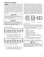
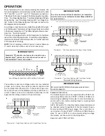
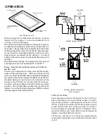
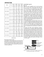
 All field wiring must conform to applicable codes.  Connections
should be made as shown in the following figure.

AUX OUT

AUX IN

L1

NEUTRAL

Accessories Wiring

If it is necessary for the installer to supply additional line volt-
age wiring to the inside of the furnace, the wiring must con-
form to all local codes, and have a minimum temperature rating
of 105°C.  All line voltage wire splices must be made inside the
furnace junction box.
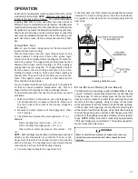
The integrated furnace control HUM (dry contacts) are closed
whenever the inducer is energized in a non-communicating
installation.  When used with a CTK02**, CTK03 or CTK04
communicating thermostat, the HUM terminals are closed
whenever there is a call for humidity.  The integrated control
module electronic air cleaner terminals (EAC) are energized with
115 volts whenever the circulator blower is energized.

24 V

OLT

 H

UMIDIFIER

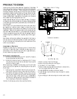
A 24 volt humidifier can be powered by feeding one of the
HUM terminals with a field installed wire from the R termi-
nal or by connecting to the NO side of the low fire pressure
switch.

Gas Supply and Piping

The furnace rating plate includes the approved furnace gas in-
put rating and gas types.  The furnace must be equipped to
operate on the type of gas applied.  This includes any conver-
sion kits required for alternate fuels and/or high altitude.

CAUTION

T

O


PREVENT


UNRELIABLE


OPERATION


OR


EQUIPMENT


DAMAGE

THE


INLET


GAS


SUPPLY


PRESSURE


MUST


BE


AS


SPECIFIED


ON


THE


UNIT


RATING


PLATE


WITH


ALL


OTHER


HOUSEHOLD


GAS


FIRED


APPLIANCES


OPERATING

.

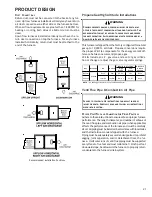
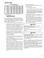
Inlet gas supply pressures must be maintained within the ranges
specified in the following table.  The supply pressure must be
constant and available with all other household gas fired appli-
ances operating.  The minimum gas supply pressure must be
maintained to prevent unreliable ignition.  The maximum must
not be exceeded to prevent unit overfiring.

Natural Gas

Minimum:    4.5" w.c.

Maximum:  10.0" w.c.

Propane Gas

Minimum:  11.0" w.c.

Maximum:  13.0" w.c.

Inlet Gas Supply Pressure

P

ROPANE

 G

AS

 C

ONVERSION

WARNING

P

OSSIBLE


PROPERTY


DAMAGE

PERSONAL


INJURY


OR


DEATH


MAY


OCCUR


IF


THE


CORRECT


CONVERSION


KITS


ARE


NOT


INSTALLED

. T

HE


APPROPRIATE


KITS


MUST


BE


APPLIED


TO


ENSURE


SAFE


AND


PROPER


FURNACE


OPERATION

. A

LL


CONVERSIONS


MUST


BE


PERFORMED


BY


A


QUALIFIED


INSTALLER


OR


SERVICE


AGENCY

.

G

AS

 P

IPING

 C

ONNECTIONS

T

O


AVOID


POSSIBLE


UNSATISFACTORY


OPERATION


OF


EQUIPMENT


DAMAGE


DUE


TO


UNDERFIRING


OR


EQUIPMENT

USE


THE


PROPER


SIZE


OF


NATURAL

/

PROPANE


GAS


PIPING


NEEDED


WHEN


RUNNING


PIPE


FROM


THE


METER

/

TANK


TO


THE


FURNACE

.

WARNING

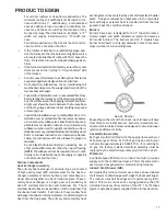
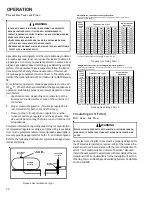
When sizing gas lines, be sure to include all appliances which
will operate simultaneously when sizing a trunk line.
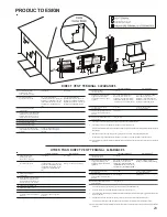
The gas piping supplying the furnace must be properly sized
based on the gas flow required, specific gravity of the gas, and
length of the run.  The gas line installation must comply with
local codes, or in their absence, with the latest edition of the
National Fuel Gas Code, NFPA 54/ANSI Z223.1.
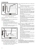
OPERATION

Summary of Contents for DM97MC

Page 1: ...mber 2016 This manual is to be used by qualified professionally trained HVAC technicians only Daikin does not assume any responsibility for property damage or personal injury due to improper service p...

Page 2: ...ERTY DAMAGE PERSONAL INJURY OR DEATH IMPORTANT INFORMATION 2 4 PRODUCT IDENTIFICATION 5 8 ACCESSORIES 9 11 LIGHTING INSTRUCTIONS 12 PRODUCT DESIGN 13 24 OPERATION 25 47 SERVICE AND OPERATION 48 OPERAT...

Page 3: ...r assistance please contact CONSUMER INFORMATION LINE DAIKIN BRAND PRODUCTS TOLL FREE 1 855 770 5678 U S only email us at customerservice daikincomfort com fax us at 731 856 1821 Not a technical assis...

Page 4: ...El mon xido de carbono puede causar enfermedades severas como da o cerebral permanente muerte Las emisiones de mon xido de carbono pueden circular a trav s del aparato cuando se opera en cualquier mo...

Page 5: ...NOMINAL INPUT 060 60 000 Btuh 080 80 000 Btuh 100 100 000 Btuh 120 120 000 Btuh AIRFLOW CAPABILITY 0 5 ESP 3 1200 4 1600 5 2000 CABINET WIDTH B 17 1 2 C 21 D 24 1 2 ADDITIONAL FEATURES N Natural Gas...

Page 6: ...tainless Steel Accessory Terminals EAC terminal HUM IN HUM OUT terminals Gas Line Entry Left or Right Revision Attributes First revision of 34 5 modulating up flow furnace MODEL DC97MC REV AA Equipmen...

Page 7: ...A Communicating Thermostat Kit Digitally communicating touchscreen thermostat a necessary part of any communicating system Designed for use with compatible Daikin Air Handlers or Furnaces and outdoor...

Page 8: ...97 upflow variable speed MVM 34 5 modulating gas furnaces This kit is intended to provide a location external to the furnace casing for installation of a permanent filter The rack is mounted over the...

Page 9: ...X DM97MC1205DN X X X X X X X X DC9 7MC060 3BN X X X X X X X X X DC9 7MC080 3BN X X X X X X X X X DC9 7MC080 4CN X X X X X X X X X DC9 7MC1005 CN X X X X X X X X Model Number 0170K00000S 0170K00001S D...

Page 10: ...vertical or horizontal vent termination The illustrations give a brief view of the kit and its application Vent Combustion Air Flush to 1 maximum 45 Elbow Field Supplied Combustion Air Vent Strap Fie...

Page 11: ...P gas as well as a set of 1 25 mm orifices to replace the factory installed natural gas orifices Do not attempt to convert a modulating furnace gas valve Factory burners are suit able for both gases L...

Page 12: ...r de gaz thislabel d allumer le br leurmanuellement ON MARCHE MANUEL EN POS explosionmayresultcausingproperty renifler tout autour del appariel pour dec ler OFF ARRET corporelles oulapertede vies huma...

Page 13: ...PPLIER WARNING IF THE INFORMATION IN THESE INSTRUCTIONS IS NOT FOLLOWED EXACTLY A FIRE OR EXPLOSION MAY RESULT CAUSING PROPERTY DAMAGE PERSONAL INJURY OR LOSS OF LIFE DO NOT STORE OR USE GASOLINE OR O...

Page 14: ...TO FIRE DO NOT INSTALL THIS FURNACE IN A MOBILE HOME TRAILER OR RECREATIONAL VEHICLE WARNING Introduction This is a Category lV furnace This furnace uses a pressur ized venting system and must be ins...

Page 15: ...inlet pipe is optional and the furnace can be vented as a Non direct vent single pipe central forced air furnace in which combustion air is taken from the installation area or from air ducted from th...

Page 16: ...erfreezeprotection Referto Condensate Drain Lines and Trap for further details Ensure adequate combustion air is available for the fur nace Improper or insufficient combustion air can ex pose building...

Page 17: ...Furnace Components Heat Exchanger Assembly The primary heat exchanger is a tubular type constructed of high quality steel 409 stainless steel for the heat ex changer assembly consists of primary and s...

Page 18: ...the IFC Aux Terminals Located next to the low voltage connector there are two terminals labeled aux in aux out A factory jumper is installed between these two terminals As an op tion the jumper may b...

Page 19: ...USTIBLE MATERIALS INCHES NOTES For servicing or cleaning a 24 front clearance is required Unit connections electrical flue and drain may necessitate greater clearances than the minimum clearances list...

Page 20: ...ces Installation Positions DM97MC models may be installed up flow or horizontally with left or right side down DC97MC models may be in stalled down flow or horizontally with left or right side down Do...

Page 21: ...e an L P gas valve and a set of gas orifices Do not change or adjust the gas valve regulator springs H igh Stage Lo w Stage Natural None 451 3 5 w c 1 w c None Propane LPM 09 1 25M M 2 1 0 0 w c 2 6 w...

Page 22: ...55 50 45 40 35 30 25 3 120 113 106 99 92 85 78 71 2 or 2 1 2 40 35 30 25 20 15 10 5 3 103 96 89 82 75 68 61 54 DC97MC1005CNA DM97MC0804CNA DM97MC1005CNA DM97MC1205DNA DC97MC0603BNA DC97MC0803BNA DC97M...

Page 23: ...corner G Clearance to inside corner H Clearance to each side of center line extended above meter regulator assembly 3 ft 91 cm within a height 15 ft 4 5 m above the meter regulator assembly OTHER THA...

Page 24: ...eezing within the drain line If an air conditioning coil is installed with the furnace a common drain may be used An open tee must be in stalled in the drain line near the cooling coil to relieve posi...

Page 25: ...ELECTRIC CODE WARNING Line voltage connections can be made through either the right or left side panel The furnace is shipped configured for a right side electrical connection To make electrical conne...

Page 26: ...tacts the furnace will be disabled until the condition is cor rected These are 24 volt terminals fed internally do not apply another voltage source to these terminals R Y C NEU Furnace Integrated Con...

Page 27: ...re may not be present on all dehumidistats 5 Turn ON power to furnace Toenablethedehumidifyfunctionontheintegratedcontrolmod ule set the dehumidification ENABLE DIP switch from OFF to ON Once the swit...

Page 28: ...THE INLET GAS SUPPLY PRESSURE MUST BE AS SPECIFIED ON THE UNIT RATING PLATE WITH ALL OTHER HOUSEHOLD GAS FIRED APPLIANCES OPERATING Inletgassupplypressuresmustbemaintainedwithintheranges specified in...

Page 29: ...5 in lbs ex cessive over tightening may damage the gas valve Install a manual shutoff valve between the gas meter and unit within six feet of the unit If a union is installed the union must be downstr...

Page 30: ...2 000 2 900 4 700 1 800 4 000 40 370 850 1 700 2 700 4 100 1 600 3 700 50 330 770 1 500 2 400 3 700 1 500 3 400 60 300 700 1 300 2 200 3 300 1 300 3 100 80 260 610 1 200 1 900 2 900 1 200 2 600 100 22...

Page 31: ...manometer to measure the static pressure of the return duct at the inlet of the furnace Negative Pressure 2 Measure the static pressure of the supply duct Posi tive Pressure 3 The difference between...

Page 32: ...lyby the installer Filters must comply with UL900 or CAN ULCS111 standards Damage or repairs due to the installation of the furnace without filters is not covered under the warranty On upflow units gu...

Page 33: ...ty Single or double digit displayed CFM X 100 MIN 57 78 80 100 IGNITION UNIT CALL FOR HEAT ENDS 10 MINS 8 MINS 2 MINS Operation with Conventional 1 Stage Thermostat DIP switch selections 1 Stage heat...

Page 34: ...Light Off Sequence After the successful Light Off Sequence and expiration of the Ignition Stabili zation Period The IFC adjusts to the low firing rate After 2 minutes the IFC accepts the specific Heat...

Page 35: ...playing Ft the display will revert back to normal 4 Measure furnace gas supply pressure with burners firing Supply pressure must be within the range specified in the Inlet Gas Supply Pressure table Na...

Page 36: ...d check out an installed appliance by bringing the furnace up to High fire 100 input by passing the normal modulating routine To enter Field Test Mode the Fault Recall Push Button must be pressed twic...

Page 37: ...the Specifica tion Sheet applicable to your model Determine and adjust temperature rise as follows 1 Operate furnace with burners firing for approxi mately ten minutes Ensure all registers are open an...

Page 38: ...or blower also offers several custom ON OFF ramping profiles These profiles may be used to enhance cooling performance and increase comfort level The ramping profiles are selected us ing DIP switches...

Page 39: ...correct setting for a conventional single stage stat or a CTK02 CTK03 and CTK04 communicating modulating stats To use a conven tional two stage heating thermostat or a CTK01 thermo stat move this swi...

Page 40: ...ds OFF ON 180 Seconds ON ON 1 Stage Stat OFF 2 Stage Stat ON 1 Stage Compressor OFF 2 Stage Compressor ON Disabled OFF Enabled ON Disabled OFF Enabled ON Disabled OFF Enabled ON Disabled OFF Enabled O...

Page 41: ...230VACto 24VAC transformer must be installed in the outdoor unit to pro vide24VACpowertotheoutdoorunit selectroniccontrol The transformer is included with the CTK01AA CTK03 and CTK04 kits See kit inst...

Page 42: ...the IFC closes the humidifier relay contacts except from the calibration routine where the humidifier relay con tacts are always open HUMIDIFIER OUTPUT COMMUNICATING THERMOSTAT One set of isolated re...

Page 43: ...ommunicating single stage thermostat The ComfortNet system is a system that includes a ComfortNet compatible furnace and air conditioner or heat pump with a CTK0 thermostat A valid ComfortNet system c...

Page 44: ...ough a calibration routine During the cali bration routine the IFC runs the induced draft blower at different speeds to determine the opening and closing points of the pressure switches It records thi...

Page 45: ...ssure switch setting Ignition Firing Rate The target firing rate at which the appliance always lights off The appliance stays at this firing rate until the Ignition Stabilization Pe riod expires It th...

Page 46: ...l reset rollout switch circuit opens during a heating cycle The valve is immediately de energized The inducer will run for the Post purge period at its current speed If the circulator fan is on it wil...

Page 47: ...losed calibration will not be completed and the ap propriate error code will be logged and displayed Hot Surface Igniter Operation The IFC energizes a relay to control the line voltage Hot Surface Ign...

Page 48: ...nnector of the diagnostic tool to the end bell communicating connector Attach one of the alligator clips of the diagnostic tool to the 24 volt hot terminal of the furnace transformer and the other all...

Page 49: ...y Use 45 elbows rather than 90 elbows when possible Must not sag or otherwise trap condensate Use longest radius fittings possible If using 3 venting make the transition from 2 to 3 as close as practi...

Page 50: ...again Safety Circuit Description A number of safety circuits are employed to ensure safe and proper furnace operation These circuits serve to control any potential safety hazards and serve as inputs...

Page 51: ...pipe system Check for blockage and or leakage Check the outside termination and the connections at and internal to the furnace Heat exchanger Check for corrosion and or buildup within the heat exchang...

Page 52: ...CONTROL 55 S 303 INDUCED DRAFT BLOWER MOTOR 55 S 304 MODULATING GAS VALVE CHECK ADJUSTMENT 55 S 304A CHECKING INDUCTOR COIL 56 SERVICING S 305 CHECKING MAIN BURNERS 57 S 306 CHECKING ORIFICES 57 S 307...

Page 53: ...RING DISCONNECT ALL POWER BEFORE SERVICING WARNING 1 Check wiring visually for signs of overheating dam aged insulation and loose connections 2 Use an ohmmeter to check continuity of any suspected ope...

Page 54: ...ter completing check and or replacement of trans former and check and or repair of control circuit re install blower compartment door 8 Turn on electrical power and verify proper unit opera tion S 300...

Page 55: ...re is being called for The power wires are colored red white and black A green colored ground wire is also present S 304 MODULATING GAS VALVE CHECK ADJUSTMENT Modulating furnaces use a 24 VAC pneumati...

Page 56: ...the appropriate range shown below If manifold pressure is found to be within the acceptable range do not adjust gas valve Natural Gas Minimum 9 w c Maximum 1 2 w c L P Gas Minimum 2 6 w c Maximum 3 3...

Page 57: ...being consumed Orifices should be treated with care in order to prevent damage They should be removed and installed with a box end wrench in order to prevent distortion In no instance should an orifi...

Page 58: ...w c Propane Gas 10 0 w c Manifold Gas Pressure S 308 CHECKING HOT SURFACE IGNITOR Modulating furnaces use a 115 volt silicon nitride hot sur face igniter This is the familiar and reliable 0131F00008S...

Page 59: ...SERVICE LISTED BELOW WARNING The ground wire must run from the furnace all the way back to the electrical panel Proper grounding can be con firmed by disconnecting the electrical power and measur ing...

Page 60: ...inuously monitored by the IFC The flame rod flame rod wire and proper grounding are all critical to proving the presence of flame Because of the design of the Honeywell flame proving system reading fl...

Page 61: ...01 0130F00482 DM97MC0804CNAA 0 10 05 0 25 0130F00481 0 17 05 0 32 0 86 05 1 01 0130F00482 DM97MC1005CNAA 0 10 05 0 25 0130F00481 0 17 05 0 32 0 86 05 1 01 0130F00483 DM97MC1205DNAA 0 10 05 0 25 0130F...

Page 62: ...ary Make sure furnace is draining properly Replaceor realign igniter Check flame sense signal Clean sensor if coated and or oxidized Check flue piping for blockage proper length elbows and termination...

Page 63: ...et thermostat scrolls Check Furnace message EC x Inducer motor overcurrent fault INDUCER FAULT OR INDUCER LOCKOUT EC x Lingering Inducer motor overcurrent detected x Reset system power and verify indu...

Page 64: ...cessary x Inspect flue and or inlet air piping for blockage proper length elbows and termination Check drain system Correct as necessary x Check induced draft blower performance Correct as necessary x...

Page 65: ...has lost communications with circulator blower motor MOTOR COMM b1 x Loose wiring connection at circulator motor control leads x Failed circulator blower motor x Failed integrated control module x Tig...

Page 66: ...omfortNet thermostat Call for Service icon illuminated x ComfortNet thermostat scrolls Check Furnace message b6 x Circulator blower motor shuts down for over or under voltage condition x Circulator bl...

Page 67: ...GE COMPRESSOR COOLING WITH DEHUMIDIFICATION WHEN 2 STAGE COMPRESSOR IS SET UP d4 INVALID MEMORY CARD DATA dF DEFROST DEMAND E0 LOCKOUT DUE TO EXCESSIVE RETRIES OR RECYCLES E1 LOW STAGE PRESSURE SWITCH...

Page 68: ...15 VAC 1 POWER SUPPLY WITH POWER BEFORE SERVICING WIRING TO UNIT MUST BE TO UNIT MUST BE PROPERLY POLARIZED EQUIPMENT GND FIELD SPLICE SWITCH TEMP SWITCH PRESSURE PROT DEVICE LOW VOLTAGE FIELD LOW VOL...

Reviews: