


cm-clic-cf-eng
www.clima-flex.com
9
Control
INPUTS AND OUTPUTS
All analog inputs of this system consist of temperature
measurements made by NTC sensors.
Table 5.
pCO Analog Inputs (Mother Unit)
Table 6.
Analog Digital Inputs of the pCO (Mother Unit)
Table 7.
pCO Digital Outputs (Mother Unit)
The configuration of the inputs and outputs depends on the initial
configuration of the system.
The tables in this section show the inputs and outputs assigned to
each type of configuration as well as the port used for the “Mother”
unit (whose capacity is regulated by a drive or an unloader) and
the “Child” units.
Key:
CO is for Cooling only and HP is for Heat Pump.
Table 8.
Analog Outputs of the pCO (Mother Unit)
Table 9.
Analog inputs of the pCOe (Expansion Module Son)
Table 10.
pCOe Digital Inputs (Expansion Module Son)
Note:
Digital motor protector inputs on “Sons” units are
optional and their consideration depends on the
initial configuration of the system, on the other
hand motor protection input on “Mother” units is
indispensable.
PORT
CO AIR
HP AIR
CO WATER HP WATER TYPE
U1
INJECTION
INJECTION
-
-
NTC
U2
RETURN
RETURN
-
-
NTC
U3
FREEZING
FREEZING
-
-
NTC
U4
MAIN RETURN
MAIN RETURN
-
-
NTC
U5
MAIN INJECTION MAIN INJECTION
-
-
NTC
U6
TEM. COND
TEM. COND
-
-
NTC
U7
-
-
-
-
NTC
PORT
CO AIR
HP AIR
CO WATER HP WATER TYPE
U9
-
SELECTOR
-
-
NTC
ID1
HIGH PRESSURE
HIGH PRES-
SURE
-
-
NTC
ID2
LOW PRESSURE LOW PRESSURE
-
-
NTC
ID3
REMOTE START
REMOTE START
-
-
NTC
ID4
MOTOR SAVER
MOTOR SAVER
-
-
NTC
PORT
CO AIR
HP AIR
CO
WATER HP WATER TYPE
NO1
COMP. STAGE
1/ VENT.
COMP. STAGE
1/ VENT.
-
-
NTC
NO6
PUMP
PUMP
-
-
NTC
NO7
SECOND STAGE
SECOND STAGE
-
-
NTC
NO8
-
REVERSIBLE
VALVE
-
-
NTC
PORT
CO AIR
HP AIR
CO
WATER HP WATER TYPE
Y1
INVERTER/SSR
INVERTER/SSR
-
-
0-10 V
PORT
CO AIR
HP AIR
CO
WATER HP WATER TYPE
B1
INJECTION
INJECTION
-
-
NTC
B2
RETURN
RETURN
-
-
NTC
B3
FREEZING
FREEZING
-
-
NTC
B4
CONDENSER
CONDENSER
-
-
NTC
PORT
CO AIR
HP AIR
CO
WATER HP WATER TYPE
DI1
HIGH PRESSURE
HIGH PRESSURE
-
-
NTC
DI2
LOW PRESSURE
LOW PRESSURE
-
-
NTC
DI3
EVAPORATION FLOW
EVAPORA-
TION FLOW
-
-
NTC
DI4
*MOTOR SAVER
*MOTOR SAVER
-
-
NTC
Table 11.
Table of Digital Outputs of the pCO (Mother Unit)
PORT
CO AIR
HP AIR
CO
WATER HP WATER TYPE
NO1
COMP.1 STAGE/FAN
COMP.1 STA-
GE/FAN
-
-
NTC
NO2
**PUMP
**PUMP
-
-
NTC
NO3
SECOND STAGE
SECOND STAGE
-
-
NTC
NO4
REVERSIBLE
VALVE
-
-
NTC
Note:
The digital output pump in “Child” units depends on
the initial system configuration.
It is not possible
to use it if the system is configured with only one
“Mother” pump (pCO unit).
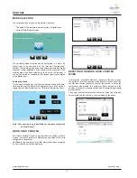
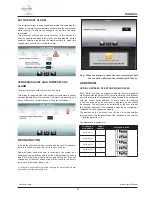
START-UP
24 V
• Place the Control switch in the ON position
to activate the 24 VAC control.
• After the control is turned on, it will take 2
minutes for the unit to come Online.
Compressor
• Place the switch in the ON position (Fig.2),
this allows the compressor to turn on and
off according to the status.
Note: Once the pump is turned on, it will take a few seconds
until a uniform flow of water is detected, at the end
of this delay, the flow switch will be monitored.
If the
switch is on it commands the pump to turn off (5
attempts within 10 seconds). If a uniform water flow
is detected the unit will begin operation.
• Under normal conditions, the equipment will turn on and off
the unit’s cooling circuit, according to its needs. When alarms
are present in the system, they will always be indicated on the
user interface.
• The digital control will start compressor operation according to
the logic set in the control.