


cm-clic-cf-eng
www.clima-flex.com
10
COMMISSIONING OF THE CONTROL LOGIC
PUMP
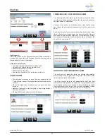
When the unit is turned on, if all safety measures are correct
(vacuum pressure, discharge, phase monitor), the pumps of all
enabled units will start.
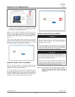
Fig. 4 shows the pump start flow diagram.
Figure 4. Flowchart of pump start-up control (applies to any unit)
Note: If the number of pump start attempts is exceeded, the
general flow alarm will be activated, this will stop
all operations on that unit until the alarm is reset.
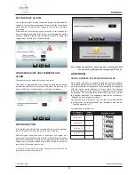
START-UP - PUMP (OPTIONAL)
The pumps in the units are always working independently of the
thermal demand, the flow detection is also constantly monitored.
If after a pause in the flow detection a change in the status of the
digital outputs is detected, the on-demand start is activated in the
unit in question. Fig. 5 shows an example of this case.
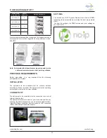
If the flow detection fails after the period allotted for digital input
detection, it is necessary to turn off the pump and restart it to make
an attempt after the waiting time between lapses has elapsed. If
after a certain number of attempts the flow is still not detected, the
“no constant flow” alarm will be activated and the unit in question
will be suspended, as illustrated in Fig. 6.
Alarma de flujo
Detección de tiempo
Bomba
Tiempo
Flujo de Entrada Digital
Figure 5. Example of the pump start-up cycle, where the flow was
detected on the second attempt.
Alarma de flujo
Tiempo de Detección
Bomba
Tiempo
Flujo de Entrada Digital
Tiempo entre intentos
Figure 6. Example of pump start-up cycle where the flow has not been
detected, after 3 attempts the flow alarm has been activated.
Note: If the system has a vane flow or thermal dispersion
sensor, the digital input for this value is a virtual
input, with a value of “1” or “OK” if the water flow is
acceptable.
REGULATION
Temperature control can be implemented in different ways, always
taking into account the system configuration. If there are “Child”
units, the temperature can be set in “Tandem” mode (all units
are coordinated by the “Mother” unit, which calculates the total
demand) or each unit can work in “Independent” mode, where each
unit calculates the local demand from its respective temperature
injection sensor (in case the main injection sensor fails).
In “Tandem” mode, the temperature control is the reading received
from the main head sensor. With this reading the total demand
is calculated. Fig.7 shows an example of the calculated demand
when the control is set to “Proportional”.
If the units are in “Independent” mode, each unit calculates its
local demand based on its temperature injection sensor. The local
demand for the “Mother” unit is generated by the same PID control
equations, while the demand for the “Child” units is a constant
reset cycle, as shown in Fig. 15.
The choice between cooling and heating (when the system was
configured with a heat pump), can be set by the digital input
“Selector” or can be made by the user. All units in a “Tandem” mode
will always work under the same mode.
The operating sequence starts with a check of
all pre-programmed safety check points, if the
necessary conditions are met, the unit is ready
to start operation.
To start operation of the unit, turn the switch to
the ON position.
On/Off (Reset)
After a few seconds the computer will send power to the water
pump. If the computer detects water flow it will command the start
of the unit’s internal control sequence.
Control
Arranque
de la
bomba
Espere a que
la entrada
digital detecte
el flujo
¿Se detectó
el flujo?
La unidad
esta lista
para iniciar
SI
NO
Se
detiene la
bomba
Tiempo de
espera entre
intentos
Flow alarm