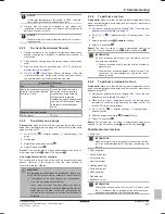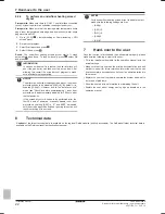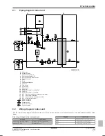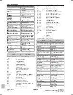
8 Technical data
Installation manual
31
C08AA
Daikin hybrid for multi heat pump – heat pump module
4P471756-1C – 2017.10
m
c
(kg)
dm=m
c
–
m
max
(kg)
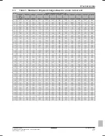
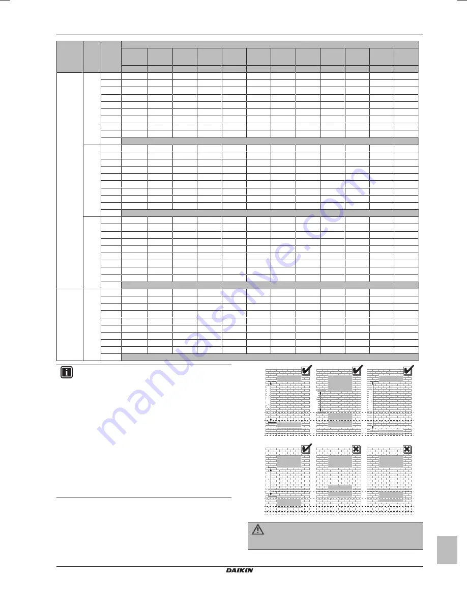
Minimum venting opening area (cm
2
)
H=500 mm,
600 mm,
700 mm
H=800 mm
H=900 mm
H=1000 mm H=1100 mm H=1200 mm H=1300 mm H=1400 mm H=1500 mm H=1600 mm H=1700 mm H=1800 mm
h=600 mm
h=700 mm
h=800 mm
h=900 mm
h=1000 mm h=1100 mm h=1200 mm h=1300 mm h=1400 mm h=1500 mm h=1600 mm h=1700 mm
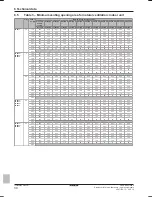
5MXM90
2.8
2.52
1025
949
888
837
794
757
725
696
671
648
628
609
2.24
911
844
789
744
706
673
644
619
597
576
558
541
1.96
797
738
691
651
618
589
564
542
522
504
488
474
1.68
786
674
592
558
530
505
483
464
448
432
419
406
1.40
732
628
549
488
441
421
403
387
373
360
349
339
1.12
642
550
482
428
385
350
322
310
299
288
279
271
0.84
520
446
390
347
312
284
260
240
224
216
210
203
0.56
371
318
278
247
223
203
186
171
159
149
140
136
0.28
197
169
148
131
118
108
99
91
85
79
74
70
0.00
3
2.70
1098
1017
951
897
851
811
777
746
719
695
673
653
2.40
976
904
845
797
756
721
690
663
639
618
598
580
2.10
881
791
740
698
662
631
604
580
559
540
523
508
1.80
872
747
654
598
567
541
518
498
480
463
449
435
1.50
812
696
609
542
488
451
432
415
400
386
374
363
1.20
712
610
534
475
427
389
356
332
320
309
299
290
0.90
577
494
433
385
346
315
289
266
247
232
225
218
0.60
411
353
309
274
247
225
206
190
177
165
155
145
0.30
218
187
164
146
131
119
109
101
94
88
82
77
0.00
3.2
2.88
1171
1084
1014
956
907
865
828
796
767
741
717
696
2.56
1041
964
902
850
807
769
736
708
682
659
638
619
2.24
970
844
789
744
706
673
644
619
597
576
558
541
1.92
960
823
720
640
605
577
552
531
511
494
478
464
1.60
895
767
671
597
537
488
460
442
426
412
399
387
1.28
784
672
588
523
471
428
392
362
341
330
319
310
0.96
635
545
477
424
381
347
318
294
273
254
239
232
0.64
453
388
340
302
272
247
227
209
194
181
170
160
0.32
240
206
180
160
144
131
120
111
103
96
90
85
0.00
5MXM90
3.3
2.97
1208
1118
1046
986
936
892
854
821
791
764
740
718
2.64
1074
994
930
877
832
793
759
730
703
679
658
638
2.31
1016
871
814
767
728
694
665
638
615
594
576
558
1.98
1006
862
754
671
624
595
570
547
527
510
493
479
1.65
937
803
703
625
562
511
475
456
440
425
411
399
1.32
821
704
616
548
493
448
411
379
352
340
329
319
0.99
665
570
499
444
399
363
333
307
285
266
250
240
0.66
474
407
356
316
285
259
237
219
204
190
178
168
0.33
252
216
189
168
151
138
126
116
108
101
95
89
0.00
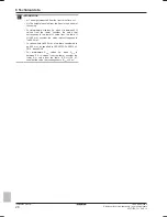
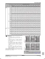
INFORMATION
▪ h=Height measured from the floor to the flare nut.
▪ H=Height measured from the floor to the bottom of the
casing.
▪ In cases where H≤600 mm, h is always considered to
be 600 mm, as specified in IEC 60335-2-40:2013 A1
2016 Clause GG2.
▪ For intermediate H values (i.e., when H is between 2 H
values from the table), consider the value that
corresponds to the lower H value from the table. If
H=950 mm, consider the value that corresponds to
"H=900 mm".
▪ For intermediate m
max
values (i.e., when m
max
is
between 2 m
max
values from the table), consider the
lower m
max
value from the table. If m
max
=1.1 kg,
consider "m
max
=0.9 kg".
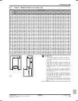
Following graphics are possible examples about minimum venting
opening area for natural ventilation.
0 mm
20 mm
100 mm
200 mm
300 mm
≥VA
min
VA
min
≥1500 mm
≥1500 mm
≥1500 mm
0 mm
20 mm
100 mm
200 mm
300 mm
≥1500 mm
≥VA
min
VA
min
WARNING
In case of a different configuration is used, do NOT deviate
from requirements mentioned in
"3 Preparation" on page 4
.

