5 Configuration
Installation manual
16
C08AA
Daikin hybrid for multi heat pump – heat pump module
4P471756-1C – 2017.10
INFORMATION
Not applicable for Switzerland.
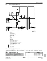
Domestic hot water pump installed for instant hot water
c
d
a
b
e
f
g
h
a
Indoor unit
b
Hot water connection on boiler
c
Domestic hot water pump
d
Shower
e
Inlet on boiler
f
Recirculation thermistor (EKTH2)
g
Water supply
h
Non-return valve
In case of [E‑06]=1
Domestic hot water pump installed for…
Instant hot water
Disinfection
c
f
b
a
g
c
b
a
d f
e g
a
Indoor unit
b
Tank
c
Domestic hot water pump
d
Heater element
e
Non‑return valve
f
Shower
g
Cold water
Thermostats and external sensors
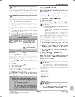
NOTICE
If an external room thermostat is used, the external room
thermostat will control the room frost protection. However,
the room frost protection is only possible if the leaving
water temperature control on the unit's user interface is
turned ON.
#
Code
Description
[A.2.2.4]
[C‑05]
External room thermostat for the
main
zone:
▪ 1 (Thermo ON/OFF): When the used
external
room
thermostat
or
heat pump convector can only send a
thermo
ON/OFF
condition.
No
separation between heating demand.
▪ 2 (H/C request): When the used
external room thermostat can send a
separate heating thermo ON/OFF
condition.
[A.2.2.5]
[C‑06]
External room thermostat for the
additional
zone:
▪ 0: N/A
▪ 1 (Thermo ON/OFF): When the used
external
room
thermostat
or
heat pump convector can only send a
thermo
ON/OFF
condition.
No
separation between heating demand.
▪ 2 (H/C request): When the used
external room thermostat can send a
separate heating thermo ON/OFF
condition.
#
Code
Description
[A.2.2.B]
[C‑08]
External sensor:
▪ 0 (No): NOT installed.
▪ 1 (Outdoor sensor): Connected to
PCB
measuring
the
outdoor
temperature.
▪ 2 (Room sensor): Connected to PCB
measuring the indoor temperature.
#
Code
Description
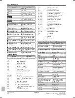
[A.2.2.6.2]
[D-07]
Solar pump station kit:
▪ 0 (No): NOT installed
▪ 1 (Yes): Installed
[A.2.2.6.3]
[C-09]
Alarm output on optional EKRP1HB
PCB:
▪ 0 (Normally open): The alarm output
will be powered when an alarm
occurs. By setting this value, a
distinction is made between the
detection of an alarm, and the
detection of a power failure.
▪ 1 (Normally closed): The alarm
output will NOT be powered when an
alarm occurs.
See also table below (Alarm output
logic).
Alarm output logic
[C-09]
Alarm
No alarm
No power
supply to unit
0 (default)
Closed output
Open output
Open output
1
Open output
Closed output
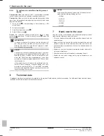
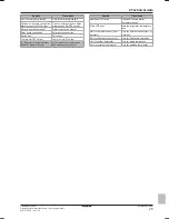
Savings mode
The user can choose whether switching between operation modes is
either economically or ecologically optimised. Set to Economical, the
system will in all operating conditions select the energy source (gas
or electricity) based on energy prices, resulting in a minimisation of
energy costs. Set to Ecological, the heat source will be selected
based on ecological parameters, resulting in a minimisation of
primary energy consumption.
#
Code
Description
[A.6.7]
[7‑04]
Defines whether switching between
operation modes is either economically
or ecologically optimised.
▪ 0 (Economical)(default): reduction of
energy costs
▪ 1 (Ecological): reduction of primary
energy
consumption,
but
not
necessarily energy costs
Primary energy factor
The primary energy factor indicates how many units of primary
energy (natural gas, crude oil, or other fossil fuels, prior to
undergoing any human-made conversions or transformations) are
needed to obtain 1 unit of a certain (secondary) energy source, such
as electricity. The primary energy factor for natural gas is 1.
Assuming an average electricity production efficiency (including
transportation losses) of 40%, the primary energy factor for
electricity equals 2.5 (=1/0.40). The primary energy factor allows you
to compare 2 different energy sources. In this case, the primary
energy use of the heat pump is compared to the natural gas use of
the gas boiler.


