background image

IM 817-4  

Page 39 of 60 

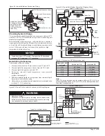
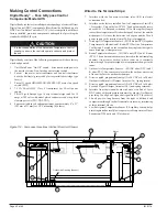
Wire Wips for Field 

Wiring  with  Caps 

(see  the  wiring 

diagram  provided 

on the unit ventilator 

right  front  access 

panel)

Field  Wiring  at 

back of Local User 

Interface  (LUI) 

Panel

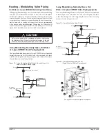
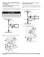
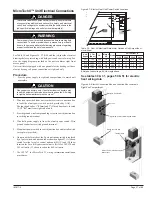
Figure 102 - Model AV - Field Wiring Whips with Caps Viewed from 

Right End Compartment 

Two  pin  plug  for  unit  mounted 

sensor

Field Wiring Remote Mounted Temperature 
Sensor

The low voltage field wiring connections have all been centrally located 

within the unit ventilator and are easily accessible.

To simplify field connections, multi-pin plugs are factory provided and 

pre-wired with short wire whips (see figure 102). Each of the wires in 

these wire whips is capped and should remain capped if not used. The 
unit mounted temperature sensor is provided with a quick disconnect 
plug (white) with wires numbered 102 and 103, and must be separated 
so that the unit mounted sensor is disconnected from the UVC. This 

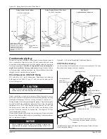
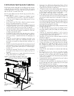
disables the unit mounted sensor (see figure 102). See Figures 103 

and 104 for wiring the remote mounted temperature sensor to the unit 
control wiring. 

All low voltage field wiring connections must be run in shielded cable 

with the shield drain wires connected as shown in the field wiring 

diagrams.

Installing the Remote Mounted Temperature 
Sensor

This describes the installation of the following three wall mounted 
sensor models:

•   P/N 111048101 – Basic

•   P/N 111048103 – Expanded ± 3

o

F setting

•   P/N 111048102 – Deluxe 54

o

F to 85

o

F setting

Use the installation instructions included with the Remote wall 
sensor.

Parts Included - All Models

•   pre-assembled sensor that includes:


- large (50.8 x 101.6 mm [2 x 4 in.]) mounting base (1)


- terminal block (1)


- 1.5 mm (1/16 in.) cover screw (1)


- endcaps (2)

•   alternate small (80 x 80 mm [3.15 x 3.15 in.]) mounting


base (1) with attached terminal block (1)

•   cover slider insert with printed logos for McQuay

®

 (1)


and AAF

®

 (1)

•   No. 6-32 x 1 in. flat-head screw (2)

•   No. 8 x 1.25 in. panhead tapping screw (2)

•   hollow plastic wall anchor (2)

Parts Included - 111048102 and 111048103 Only

•   alternate serrated setpoint dial (attached)

•   smooth setpoint dial (separate)

Special Tools Needed

•   .5 mm (1/16 in.) Allen wrench

•   7 mm (1/4 in.) flat-blade screwdriver

•   hole saw with 35 mm (1-3/8 in.) blade (for surface mounting  

  only)•

•  drill with 8 mm (5/16 in.) drill bit (for surface mounting only)

The unit comes with a unit mounted sensor and does not require 
a remote wall mounted sensor.

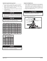
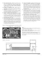
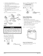
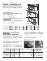
Figure 104 -  Wall Mounted Temperature Sensor Wiring for Expanded 

and Deluxe Wall Sensor

BLK

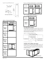
Static sensitive components. A static discharge while handling 
electronic circuit boards can cause damage to the components.
Discharge any static electrical charge by touching the bare metal 
inside the main control panel before performing any service work. 
Never unplug any cables, circuit board terminal blocks, relay 
modules, or power plugs while power is applied to the panel.

Figure 103 - Wall Mounted Temperature Sensor Wiring for Basic Wall 

Sensor

896

P 1

C o n n e c t o r

B L K

WHT

R E D

Wire

C a p s

Unit Ventilator

LED

Comm

AI-1

AI-2

GND

6

4

3

2

5

1

Setpt. Adj.

C o m m

S e n s o r

LED

Wall Sensor

(option)

S h i e l d

Field Wiring (by Others)
E x t e r n a l   D e v i c e   ( b y   O t h e r s )

Factory Wiring

GRN


CAUTION


NOTICE

Summary of Contents for AVB

Page 1: ...elop a thorough understanding before starting the installation procedure This manual is to be used as a guide Each installation is unique so only general topics are covered The order in which topics are covered may not be those required for the actual installation C Installation Manual IM 817 4 Group Unit Ventilator Part Number 106506225 Date October 2013 IMPORTANT 2013 Daikin Applied www DaikinAP...

Page 2: ......

Page 3: ...6 Typical Steam Coil Piping 26 Heating Modulating Valve Piping Hot Water or 2 pipe CW HW Modulating Valve Piping 27 2 way Modulating Normally Open Hot Water or 2 pipe CW HW Valve Piping typical 27 3 way Modulating Normally Open Hot Water or 2 pipe CW HW Valve Piping typical 27 Cooling Chilled Water Modulating Valve Piping 2 way Modulating Normally Closed Chilled Water Valve Piping typical 28 3 way...

Page 4: ...um Grilles Auxiliary Drain Pans Controls Sensors End Panels Spare Filters MicroTech II Controls Remote Wall Sensors temperature End of Cycle DDC Valve Modulating DDC Valves Subbases See instructions shipped with accessories and install according to these and the plans 1 Product Category U Unit Ventilator 2 Product Identifier AVS Floor Face and Bypass Damper Heat Cool Heat Only Cool Only AVV Floor ...

Page 5: ...ult if improper lifting and moving methodsareused Seetable2 page3forapproximateshipping weights Use 72 length forklift tines short tines will damage the unit bottom Improper handling can damage internal components Do not stand the unit on end or stack see figure 2 3 ModelAV Floor Unit Ventilator Installation Models AVV AVR AVS AVB and AVR Receiving Handling This product was carefully packed and th...

Page 6: ... packaging to provide jobsite unit location information and temporary protection for the unit ventilator after installation Be sure to dispose of plastic packaging and protective cardboard properly in accordance with local recycling rules and guidelines If unit is damaged file a claim with the carrier Notify the local Daikin Unit Ventilator representative immediately Wall Openings Louvers and Vent...

Page 7: ...uver Horizontal Blade Louver Flange Flange Outside Air Outside Air Outside Air Bird Screen On Side Toward Unit Vertical Louver with Flange without Grille Horizontal Louver without Flange with Grille Locate Drain Lip at bottom of vertical louver to allow proper drainage For horizontal louvers the louver blades should face down for proper drainage Bird screen should always be on side toward unit Bot...

Page 8: ...r AL With Accessory Closed Pipe Tunnel Piping Floor Line Lintel By Others Intake Louver Not Less Than 3 Not More Than 28 Insulated Closure Plate Accessory Provide Drainage Important Gasket sealing surface is required Figure 12 Floor Level Outdoor Air Intake With Window Below Unit Top Using Arrangement AL And 9 Finished Painted Accessory Uninsulated Closed Pipe Tunnel Unit Configuration Type AL Lin...

Page 9: ...ealing surface is required Lintel By Others Piping Floor Line Sealed Cement Mortar Pitch Away From Unit Important Gasket sealing surface is required Louver Lintel By Others Piping Piping Important Gasket sealing surface is required Piping Piping Important Gasket sealing surface is required Louver Installation With Typical Unit Configurations Lintel By Others Gasket Seal Intake Louver Piping Piping...

Page 10: ...op and the two vertical sides of the louver leaving the bottom uncaulked so that if moisture gets into the area between the louver and the unit it can drain to the outside unrestricted If the louver is supplied with flanges see figure 20 place an additional bead of caulk on the inside of the top and side flanges that come in contact with the building facade Do not caulk the bottom flange Place the...

Page 11: ...re 19 Suggested method for fastening louver without flange inside wall opening Figure 22 Louver VentiMatic Shutter Interior Wall Grille Details Dimensions As Directed By Architect 3 4 19mm Approx 7 178mm Cement Mortar Steel Interior Wall Grille Optional See Note 3 125 8 314mm 3 4 19mm Approx Bird Screen Do Not Block Drain Holes With Caulk or Mortar Not Less Than 9 229mm Cement Mortar C see table 3...

Page 12: ...Leakage of outdoor air wastes energy causes drafts and erratic unitventilatoroperation Checkthefollowingdetails Atthecorrect unit ventilator location examine the wall surface Make sure that it is smooth plumb and perpendicular to the floor The seals on the rear of the unit ventilator will take up the small irregularities found in normal masonry construction If the wall is irregular or has mullions...

Page 13: ...1 279 mm Front V iew of End Compartment Without End Panels 4 3 4 121 mm Personalinjuryhazard Wearprotectivegloves toavoidpossible cuts and abrasions from exposed edges Avoid contact with sharp edges Figure 30 Low End of Drain Pan Drain End Overflow Connection Standard Drain Connection 1 4 hex head screws Disconnect all electrical power before servicing unit to prevent injury or death due to electr...

Page 14: ...s Caulk Top And Two Sides Of Louver Sealed Mortar Bed Caulk Weep Holes Floor Unit Insulating Blanket Back Of Unit Unit Bottom Gasket Seal Under Unit Bird Screen Internal Column For Wall Bracing By Others Unit Gasket Louver Unit Ventilator Outdoor Air Opening Outside Roomside Typical VentiMatic louver installation with shelving Outside Roomside VentiMatic Shutter Assembly Building Wall Typical Floo...

Page 15: ... identification In addition to all seismic requirements for IBC Certification listed elsewhere in the project specification submittals for these units include 1 A Certificate of Compliance from the Independent Certifying Agency clearly indicating that components supplied on this project are included in the component manufacturer s Certificate of Compliance 2 Clear installation instructions includi...

Page 16: ...proper insulation of supply and return piping Proper insulation preventslossofunitventilatorcapacity overheatingofendcompartment and or moisture dripping The piping to and from the unit must be protected from outside air and freezeconditions Thepipingmustbesuitablyinsulatedforcondensation or heat lose or gain Penetrations entering the unit end compartments must be fitted sealed for unit integrity ...

Page 17: ...ections Figure 39 Chilled Water Coil Connections Failure to install water piping to coils properly can result in improper unit operation and coil freeze ups Figure 40 Protect Components From Overheating Before Brazing Use A Quenching Cloth When Brazing to Prevent Overheating The Piping Components Avoid Valve D a m a g e a n d E r r a t i c Operation Vent Drain Plug 2 pipe Chilled Water Hot Water S...

Page 18: ...nections and terminate 9 229mm from the end of the unit 9 DXcoils G haveO D sweatconnections Interconnectingtube by others See table 7 for correct tubing size Table 6 Dimensions Table 7 DX Coil G Connection Tubing L H Connections Electric Heating Only S Supply R Return R H Connections L H Connections R H Connections R H Connections Table 4 Heating Only Coil Position Combinations In Air Stream one ...

Page 19: ...pansion G and Steam Unit Cooling Coil G Heating Coils 68 69 78 79 Figure 52 Direct Expansion and Electric Heating Cooling Coils G Heating Coils 12 13 Right Hand Right Hand Cooling Left Hand Heating Right Hand Figure 53 Chilled Water 1st Position and Electric Heating Cooling Coils V S W Heating Coils 12 13 Right Hand Note For opposite end drain steam coils code 78 79 Return R is 71 4 184mm from bot...

Page 20: ...ure 58 Direct Expansion G and Steam Unit Cooling Coil G Heating Coils 68 69 78 79 Figure 54 Chilled Water and Hot Water Unit Cooling Coils S W V Heating Coils 65 66 67 Figure 55 Chilled Water and Steam Unit Cooling Coils S V Heating Coils 68 69 78 79 Figure 56 Chilled Water and Electric Heating Cooling Coils V S W Heating Coils 12 13 Figure 59 Direct Expansion and Electric Heating Cooling Coils G ...

Page 21: ...ead pressure is required 6 All water coil stubs are 7 8 I D female sweat Coil connections terminate 9 229mm from the end of the unit Hot water connections may be same end as cooling coil connections but are recommended to be at opposite ends from each other When using MicroTech II controls they must be at opposite ends Face and Bypass MicroTech II 2 Way and 3 Way End of Cycle Valves Control 2 Posi...

Page 22: ...Way Modulating Valve Actuators Table 16 Valve Body Specifications 400 psig 2 756 PA up to 150o F Water 66o C decreasing to 365 psig Static 2 515 kPa at 248o F 120o C Pressure 38 psig 262 kPa Saturated steam at Steam 284o F Fluid Temperature 35 to 250o F 2 to 121o C 15 psig 103kPa saturated steam Table 15 Actuator Specifications 2 Way Modulating Valve 3 Way Modulating Valve Valve Size in DN A B C N...

Page 23: ...orrectly select the proper Hot Water or Chilled Water Modulating Valve 1 Determine the flow of water and the corresponding pressure drop through the coil 2 Obtain the pressure difference between the supply and return mains 3 Select a valve size Cv from Table 19 on the basis of taking 50 of the available pressure difference at design flow between the supply and return mains at the valve location Th...

Page 24: ... Valve Piping S5 Sensor 2 pipe CW HW Units Only Typical Piping Arrangements Heatingvalveactuatorsshouldbemountedinanuprightpositionabove the centerline of the valve body and should be piped normally open to the coil Modulating valve actuators for hot water applications may be positioned above the valve body a maximum of 75º from the vertical Forsteamapplicationsonly mountthemodulatingvalveactuator...

Page 25: ...ally open to the coil When the valve is de energized off there is full flow through the coil Energizing the valve reduces the steam flow in a modulating fashion Refer to the arrow on the modulating valve body to determine the direction of flow If the valve is mounted improperly the unit will not operate properly and damage to the valve may result The valve should be installed so that there is a 2 ...

Page 26: ...re 1 1 8 34mm female sweat connections Coil connections terminate 9 229mm from the end of the unit Steam coils have a factory installed pressure equalizing valve and a 24 610mm long pressure equalizing line that terminates in a 1 2 M P T fitting Steam connections may be same end as cooling coil connections but are recommended to be opposite end to facilitate piping When using MicroTech II controls...

Page 27: ...g Valve N O Common N C Whenpipingthemodulatingvalve refertothearrowsonthemodulating valve body to determine the direction of flow The valve should be installed so that there is a 2 51mm minimum clearance to remove the actuatorformthevalvebody Provideunionsforremovalofunitcoiland orcontrolvalveasafutureserviceconsideration Hotwaterconnections may be same end as cooling coil connections but are reco...

Page 28: ... Supply Supply 2 way Modu lating Valve Unit Coil Unions Return Shutoff Valve Supply Supply 3 way Modulating Valve Union Balancing Valve N C N O Return Unit Coil Union Common Balancing and Shutoff Valve Figure 84 3 way Modulating Valve Control Piping Within Unit End Compartment 11 2 3 4 5 6 7 8 15 S5 Sensor Refer to the arrows on the modulating valve body to determine the direction of flow If the v...

Page 29: ...en Brazing to Prevent Overheating The TXV Valve Body Avoid Valve Damage and Erratic Operation Figure 86 TXV Valve Piping Detail Left Hand Shown Proper ventilation is required for brazing When brazing be sure to protect unit ventilator components from overheating damage melting insulation also damage to valves wiring electronics sensors etc Duringbrazing bleednitrogenthroughthepiping Usingfield sup...

Page 30: ...ts the system under low refrigerant suction conditions see figure 90 UVfans must continue to run upon Low RefrigerantTemperature trip of T4 controls by others or S4 MicroTech II evaporator air flow dissipates residual low coil surface temperatures suction pressures raised coil frosting reduced see figure 90 UVfansmustcontinuetorunforsettimeperiodduringunoccupied modeaftersatisfactionofthespacesens...

Page 31: ...Unit Ventilator High Pressure Gauge Figure 90 Typical Unit Ventilator Condensing Unit Wiring Diagram Compressor Compressor Contactor Capacitor Head Pressure Controller Optional Fan Motor High Pressure Switch Low Pressure Switch TDR Time Delay Relay TB Terminal Block T4 2 3 1 Rec3 LineVoltage Factory Wired Field Wired By Others TDR or TB LowAmbient Temp Switch To controls by others to energize cond...

Page 32: ...mbient conditions Each time that charge is added or removed from the system allow the system to run approximately 20 30 minutes before pressure and temperature readings are taken and superheat calculations made If system hunting occurs or subcooling is reduced it may be necessary to adjust TXV to obtain correct superheat Superheat Adjustment 1 Remove the seal cap from thermal expansion valve see f...

Page 33: ...ontrol device capable of complete Standalone unit control Master Servant control or incorporatedintoabuilding widenetworkusinganoptionalplug in communicationmodule TheUVCcontainsamicroprocessorthat ispreprogrammedwiththeapplicationcoderequiredtooperatethe unit The UVC supports up to 6 analog inputs 12 binary inputs and 9 binary outputs The UVC EXP I O board supports up to 4 additional analog input...

Page 34: ...000 ppm and voltage output of 0 to 10 VDC 100 ohm output impedance The Pitot Tube sensing device is located in the unit ventilator s return air stream The optional CO2 sensor is used with the UVC s Demand Control Ventilation feature to vary the amount of outside air based on actual room occupancy With network applications the unit mounted sensor can be overridden by a remote sensor through the net...

Page 35: ...cted with7keys 1keyishidden and9individualLEDindicators to adjust the unit ventilator operating parameters shown below Operating Mode States 4 Heat Heating and economizer operation only Cool Cooling and economizer operation only Fan Only Fan operation only Auto Unit automatically switches between heating cooling and economizer operation to satisfy the room load conditions The current unit state is...

Page 36: ...BLU BRN BRN BLK LOW BLU WHT BLU BLU BRN HI BLU 1 3 HP MED BLU WHT LOW YEL HI RED RED RED RED RED 1 2 HP MED BRN BRN BRN BLK BLU LOW YEL YEL YEL YEL BLK Figure 96 DE Cooling W Hot Water Heat Damper Control 115 208 230 265 Volt 1 Phase CAUTION DISCONNECT ALL ELECTRICAL POWERBEFORESERVICINGUNIT TO PREVENT INJURY OR DEATH DUE TO ELECTRICAL SHOCK USE COPPER CONDUCTORS ONLY UNIT TERMINALS ARE NOT DESIGN...

Page 37: ... 7 Use IM 747 for MicroTech II wiring information installation procedures Table 24 Floor AV Electrical Data Motor Data and Unit Amp without electric heat Unit CFM L s Motor Unit Current Series Nom HP Watts 115V 208V 230V 265V S07 750 354 1 4 164 1 8 1 0 0 9 0 8 S10 1000 472 1 4 244 3 1 1 7 1 5 1 3 S13 1250 590 1 4 306 3 5 1 9 1 8 1 5 S15 1500 708 1 4 334 3 7 2 0 1 8 1 6 Amps at unit voltage 60 Hz ...

Page 38: ... and Wall Sensor Locations Figure 99 Basic Remote Wall Sensor LED Tenant Override Button Sensor All MicroTech II equipped unit ventilators are provided as standard with a unit mounted space temperature sensor The unit mounted temperature sensor is provided with a quick disconnect plug white located outside of box with numbered wires 101 and 102 When using a remote wall mounted temperature sensor t...

Page 39: ...tions included with the Remote wall sensor Parts Included All Models pre assembled sensor that includes large 50 8 x 101 6 mm 2 x 4 in mounting base 1 terminal block 1 1 5 mm 1 16 in cover screw 1 endcaps 2 alternate small 80 x 80 mm 3 15 x 3 15 in mounting base 1 with attached terminal block 1 cover slider insert with printed logos for McQuay 1 and AAF 1 No 6 32 x 1 in flat head screw 2 No 8 x 1 ...

Page 40: ...ing base 3 Loosen the cover screw using a 1 5 mm 1 16 in Allen wrench and remove the sensor 4 Drill a 35 mm 1 3 8 in hole in the surface where the sensor will be mounted 5 Pull the cable or wiring through the hole 6 Rotate the mounting base until one of the arrows on the base points up If necessary reposition the cover screw abovethearrow Placethebaseagainstthewall andmarkthescrew holes using the ...

Page 41: ...shielded cable generallyisnotrequired exceptinelectricallynoisyenvironments such as near gas ignition systems radar or magnetic resonance imaging equipment etc It is the responsibility of others to determine what constitutes an electrically noisy environment for each installation Refer to table 25 page 38 for maximum wire length 6 Pull the cable or wiring through the hole 7 Place the small base ag...

Page 42: ...tory installed Low Air Temperature Limit T6 Freezestat Cuts out below 38o F 2o F and automatically resets above 45o F 2o F Responds when any 15 of the capillary length sensesthesetemperatures WiredsothatuponT6cutout theoutside air damper A1 closes the hot water valve opens and the 24 volt power supply to the terminal strip T6 Sig is interrupted 9 DischargeAirTemperatureSensors S2 10KohmNTC Negativ...

Page 43: ...IM 817 4 Page 43 of 60 Refer to unit wiring diagram located on the right front panel for actual wiring Digital Ready Wiring Diagram Typical Figure 113 Face and Bypass Control CAUTION ...

Page 44: ...ion of a Belimo ZG R01 or equivalent 500 ohm resistor by others Refer to the wiring diagram for proper installation of the resistor A 2 to 10 VDC output signal is provided for damper position feedback Rotation is clockwise to open OA close RA Face and Bypass Damper Actuator The Face Bypass damper actuator is a unit mounted direct coupled non spring returned actuator used for the modulation of the ...

Page 45: ...ent and Terminal Strip Figure 116 Terminal Strip Use copper conductors only Use of aluminum conductors may result in equipment failure and overheating hazards All wiring in right hand compartment must be class 1 4 Wire field power supply to line side of unit power switch Wire ground conductor to switch ground terminal 5 Mount unit power switch in switch junction box and install switch cover plate ...

Page 46: ...matic Temperature Control supplier to ensure the controls operates correctly and protect the unit Controls by others option consists of the following components which are factory provided and wired where indicated 1 Unit Main Power On Off switch disconnects main power to the unit Non fused power interrupt switch S1 2 Fan motor auto transformer and control transformer have the hot line s protected ...

Page 47: ...r actual wiring Improper wiring can cause equipment and property damage CAUTION Disconnect all electrical power before servicing unit Electrical shock will cause severe injury or death DANGER WARNING Hazardous Voltage Use copper conductors only Unit terminals are not designed to accept other types of conductors Failure to do so may cause damage to the equipment ...

Page 48: ...ntrol units B is for 208 230 and 265 volt units C shows location for 460 volt units Also on electric heat units with controls by others wiring to the field mounted controller is done in the left end compartment See specific wiring diagram for details The unit comes with wiring that requires relay controls by others It is the responsibility of the Automatic Temperature Control suppliertoensurethatt...

Page 49: ...tric Heat Wiring Diagram Typical Figure 123 460 Volt 60 Hz 3 Phase Refer to unit wiring diagram located on inside of right front panel for actual wiring Improper wiring can cause equipment and property damage CAUTION DISCONNECT ALL ELECTRICAL POWER BEFORE SERVICING UNIT TO PREVENT INJURY OR DEATH DUE TO ELECTRICAL SHOCK USE COPPER CONDUCTORS ONLY UNIT TERMINALS ARE NOT DESIGNED TO ACCEPT OTHER TYP...

Page 50: ...ate s Powersupply to unit must be disconnected when making field connections Rigorously adhere to field wiring procedures regarding proper lockout and tagout of components Electric Heating Table 30 Standard Motor Electric Heat Capacities Amps Wire Sizing and Over Current Protection Amps at unit voltage 60Hz single phase Note Unit wire sizing should be determined in accordance with NEC and local co...

Page 51: ...IM 817 4 Page 51 of 60 Electric Heating Table 31 High Static Applications Electric Heat Capacities Amps Wire Sizing and Over Current Protection Note Electric heat disconnect provided ...

Page 52: ...oyed even in those marginal applications to provide the occupants comfort without the material installation and operating cost penalty associated with auxiliary radiation The unit ventilator is ordered with the return air intake having a draftstop blockoff to restrict return air flow through the front bottom unit opening option 30 in field 11 of the model number Thisallowsdrawingofreturnairthrough...

Page 53: ... wall trim rest in the top groove of the upper channel 3 Wall to EndApplication Runtheupperchannelorbackplatefrom the wall to a point where the enclosure will end See Draftstop installation instructions for details of end cap installation 4 End to End Application Run the upper channel or backplate the samelengthastheenclosure SeeDraftstopinstallationinstructions for details or end cap installation...

Page 54: ...133mm Step Down Top View 28 711mm 6 152mm End View With No Cut out Table 34 6 152mm End Panel Dimensions 28 Non Standard Floor Unit Ventilators Floor Figure 129 Typical DraftStop Enclosure Mounting Channel Detail Open 3 8 10mm Max Screw By Others 11 4 32mm 2 51mm Enclosure Slide Closed 12 305mm 20 508mm 24 610mm 53 8 31 8 277 8 708mm 277 8 708mm 22 559mm 4 102mm 1 25mm 28 711mm 1 25mm 277 8 708mm ...

Page 55: ... Tinnerman Clips Tinnerman Clips Screws insert through end panel and thread into tinnerman clips on unit subbase Screws insert through upper mounting holes inside unit end compartment and thread into tinnerman clips on end panel End Panel w Cut out Figure 132 Install End Panels With Provided Hardware 1 End Panel Shown Figure 133 Install End Panels With Provided Hardware 6 End Panel Shown NOTICE Re...

Page 56: ...and Start Procedure Included in the shipping envelope in the end compartment of the unit Provide completed Check Test and Start procedure to local Daikin representative and to specifying engineer to verify proper start up was completed Electric heat units should ONLY use permanent wire mesh filters Filters other than wire mesh are not intended for electric heat units and can cause unit damage prop...

Page 57: ......

Page 58: ......

Page 59: ......

Page 60: ... to its standard terms and conditions of sale including Limited Product Warranty Consult your local Daikin Representative for warranty details Refer to Form 933 430285Y To find your local Daikin Representative go to www DaikinAP com Aftermarket Services To find your local parts office visit www DaikinAP com or call 800 37PARTS 800 377 2787 To find your local service office visit www DaikinAPcom or...

Reviews: