background image

IM 1083 

Self-Contained WSHP Unit Ventilator Models ARQ, ERQ, GRQ  

Page 39 of 42 

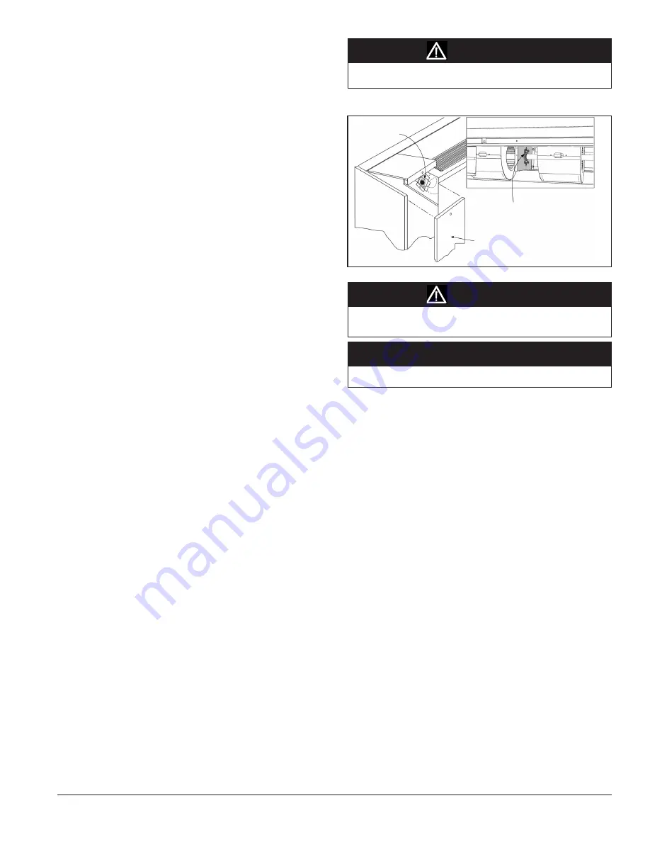
Figure 74:  Fan Shaft Bearing(s) Oil Cup Location(s)

Room Air Fan 

Shaft Bearing

Left Front Access Panel

Prepare Unit Ventilator for Start-up

Post Installation Checklist

  Unit securely fastened to wall


Electrical hook-up complete; power, control, wall 

thermostat (if applicable) in accordance with unit wiring 

diagram(s)


Air filter clean and in place


  All access and end panels in place and protective 

covering removed

  No debris, dust, dirt, or obstructions exist in front of 

the return air intake grille at the floor

  All installation work has been completed in 

accordance with applicable local, state and national 

codes


  Room air fan shaft bearing oiled

  Unit square and level and running smoothly and 

quietly


□  No air infiltration

  Paint nicks and scratches touched up (as required)

  Access space provided for maintenance, service and 

unit removal

□  Shipping carton replaced over unit for protection

  Owner or maintenance personnel provided with a 

copy of this manual and other manuals/documents 

shipped with the unit.

□  Owner or maintenance personnel instructed on 

proper operation and maintenance

Oiling

Do not attempt to operate the unit fans until the room air fan shaft 

bearing has been oiled. 

Access to fan shaft bearing is through left top access door. Use a high 

grade SAE 20 or 30 nondetergent mineral oil. A few drops are sufficient. 

Do not over oil.

 Refer to Figure 74 for the oil point. 

Note:

Unit size 048 has a fan shaft bearing located between the first 

and second fan from the unit left end that is required to be oiled.

Filter(s)

AAF

®

-HermanNelson

®

  single-use  filters  are  standard  on  all  units. 

Permanent wire mesh and renewable media filters are available in lieu 

of single-use filters.
•  Single-use filters feature Amerglas media. They are designed to be 

used once and discarded.

•  Permanent filters are metal filters that may be removed for cleaning 

and reused numerous times.

•  Renewable media filters (figure 75) consist of a heavy painted metal 

structural frame and renewable Amerglas media.

Turn off unit before servicing to avoid danger of injury from 

rotating fans. 

WARNING

Motor manufacturer recommends not oiling the room fan motor.

NOTICE

When oiling the middle fan shaft bearing DO NOT allow oil to 

drip down on the components located below the bearing.

CAUTION

Unit  Size  048  Bearing,  Located 

Between First and Second

Fan from Left End of Unit

Summary of Contents for ARQ

Page 1: ...in its entirety Develop a thorough understanding before starting the installation procedure This manual is to be used as a guide Each installation is unique so only general topics are covered The order in which topics are covered may not be those required for the actual installation C Installation Manual IM 1083 Group Unit Ventilator Part Number 106506250 Date October 2013 IMPORTANT 2013 Daikin Ap...

Page 2: ......

Page 3: ...16 Before Sliding the Unit into Place 16 Installing Casters 16 Reversing Condensate Drain End 17 Mounting Hole Locations Dimensions 17 18 Operating Limits 19 Piping Considerations 20 Water System Cleaning 21 Make Piping Connections 22 Water Coil Connections 22 23 System Balancing 23 Making Control Connections 24 MicroTech II Unit Mounted DDC Control Components 24 26 Typical Wiring Diagram 27 DX Co...

Page 4: ...nels Spare Filters MicroTech II Remote Wall Sensors temperature End of Cycle DDCValve See instructions shipped with accessories and install according to these and the plans 1 Product Category U Unit Ventilator 2 Product Identifier ARQ SC Standard Range WSHP 60 F EWT Ultra Quiet ERQ SC Extended Range WSHP 50 F EWT Ultra Quiet GRQ SC Geothermal RangeWSHP 20 F EWTGround Source Ultra Quiet End panels ...

Page 5: ...me apparent until the product has been unpacked The contents may be damaged in transit due to rough handling even though the carton may not show external damages When the damage is discovered upon unpacking make a written request for inspection by the carrier s agent within fifteen 15 days of the delivery date File a claim with the carrier since such damage is the carrier s responsibility Storage ...

Page 6: ...ans Figure 4 Shipping Envelope Contents Located in right end compartment of unit Safety Follow all safety codes Wear safety glasses and work gloves Use a quenching cloth for brazing operations Have a fire extinguisher available Follow all warnings and cautions in these instructions and attached to the unit Consult applicable local building codes and National Electrical Codes NEC for special requir...

Page 7: ... others Weep Holes Caulk Top And Two Sides Of Louver Sealed Mortar Bed Caulk Weep Holes Floor Unit Insulating Blanket Back Of Unit Unit Bottom Gasket Seal Under Unit Bird Screen Internal Column For Wall Bracing By Others Unit Gasket Louver Unit Ventilator Outdoor Air Opening Outside Roomside Typical VentiMatic louver installation with shelving Outside Roomside VentiMatic Shutter Assembly Building ...

Page 8: ...endent Certifying Agency s name and report identification In addition to all seismic requirements for IBC Certification listed elsewhere in the project specification submittals for these units include 1 A Certificate of Compliance from the Independent Certifying Agency clearly indicating that components supplied on this project are included in the component manufacturer s Certificate of Compliance...

Page 9: ...Louver VentiMatic Shutter Roomside Relief Air WallOpenings Louvers andVentiMatic Shutter Self Contained Floor Models ARQ ERQ GRQ are typically installed in front of a wall opening containing a properly sized louver that is designed to let in outside air while preventing water such as rain from getting past the louver and into the unit itself A weather tight seal keeps unwanted air and moisture fro...

Page 10: ...tant Gasket sealing surface is required Important Gasket sealing surface is required Lintel By Others Unit Refrigerant Piping Floor Line Lintel By Others Intake Louver Not Less Than 3 Not More Than 28 Insulated Closure Plate Accessory Provide Drainage Important Gasket sealing surface is required Figure 14 Floor Level Outdoor Air Intake With Window Below Unit Top and 9 Finished Painted Accessory In...

Page 11: ... Pitch Away From Unit Important Gasket sealing surface is required Louver Lintel By Others Unit Refrigerant Piping Field Supplied Water Piping Unit Refrigerant Piping Field Supplied Water Piping Important Gasket sealing surface is required Louver Installation With Typical Unit Arrangements 21 Unit Depth Lintel By Others Gasket Seal Floor Line Floor Line 1 25mm 1 25mm Sealed Cement Mortar Pitch Awa...

Page 12: ...venting freeze ups cold drafts and air infiltration Be sure the wall is smooth square and provides a suitable mating surface Beforesettingthelouver constructasloping sealedcementmortarbase to drain unwanted moisture to the outside see figure 20 Be sure the mortar base is 1 25mm thick at the unit and tapers toward the louver The mortar at the unit also acts as a backing against which the open cell ...

Page 13: ...de or as directed in the architectural plans If specified in the plans secure the louver in the wall using mechanical fasteners supplied by others appropriate to the installation See figure 22 for suggested fastening With the louver solidly in place run a bead of caulk around the perimeter of the louver to seal it weather tight Do not plug the weep holes horizontal louver or the drip line vertical...

Page 14: ... Not Less Than 9 229mm Cement Mortar C see table 4 Aluminum Wall Louver Assembly With Bird Screen See Note 1 B see table 4 Steel VentiMatic Shutter Assembly 41 8 105mm 237 8 606mm or 357 8 911mm 2 51mm 103 8 264mm 3 76mm Decorative Exterior Grille Also Available See Note 2 above Bird Screen not shown Figure 26 Single VentiMatic Shutter Wall Louver Outside Aluminum Wall Louver Assembly with Bird Sc...

Page 15: ...tside Roomside Typical VentiMatic louver installation with shelving Outside Roomside VentiMatic Shutter Assembly Building Wall Installing VentiMatic Shutter The VentiMatic shutter assembly mounts on the same wall as the unit ventilator louver to neutralize wind effect Closed Shelf Storage Cabinet with Slotted Kickplate Cabinet Slotted Kickplate ...

Page 16: ...rward up to the wall When the unit is in position reverse the procedure and remove the caster kit Save the caster kit for future unit servicing or replacement Figure 31 Optional Indoor Section Caster Installation Raises and low ers casters two on compressor end of unit Raises and lowers caster Caster mounting cut out Right Caster Left Caster Clockwise to raise Counter clockwise to lower Preparing ...

Page 17: ... the drain pan 5 Verify the drain connection is open on the low drain right end only The open drain connection stub outs at the high end of the drain pan left end must be sealed water tight with silicone sealer or similar To Clean the Drain Pan 1 Removetheshallowanddeepupperplatesfromtheunit seefigures 32 and 33 2 Spray water into the drain pan on the high end to wash debris to the low end drain e...

Page 18: ...gure 35 and attach the unit ventilator to the wall through the four 4 mounting holes provided using field supplied fasteners appropriate to the wall construction and the washers provided in the brown envelope with these instructions Envelope also contains allen wrenchtoprovideaccesstounit Pushtheunitventilatortighttothewall structure so that the outdoor air seals are compressed Secure the wall fas...

Page 19: ... Range Units Units Cooling Heating Cooling Heating Min Ambient Air 50 F 50 F 40 F 40 F Normal Ambient Air 80 F 70 F 80 F 70 F Max Ambient Air 100 F 85 F 100 F 85 F Min Entering Air 1 2 50 F 50 F 50 F 40 F Normal Entering Air db wb 80 67 F 70 F 80 67 F 70 F Max Entering Air db wb 1 2 100 83 F 80 F 100 83 F 80 F Additional Information For Initial Start up Standard Range units Units are designed to s...

Page 20: ... via short lengths of high pressure flexible hose which are sound attenuators for both unit operating noise and hydraulic pumping noise One end of the hose should have a swivel fitting to facilitate removal for service Hard piping can also be brought directly to the unit This option is not recommended since no vibration or noise attenuation can be accomplished The hard piping must have unions to f...

Page 21: ... early in this procedure as they are discovered With valves positioned to bypass the heat pumps heat rejector and the supplementary water heater the pump should be startedtocirculatewaterthroughthesystem Checkstrainersfrequently and clean as often as needed If the water is extremely dirty or murky it is sometimes helpful to continuously flush using the system pump until the water being flushed out...

Page 22: ...evalvebody Becertainthatthecontrolvalveisinstalledcorrectly withitsorientation vertical Valves should be installed at least 5 off center Be certain that the control valves are installed with the proper port orientation to provide proper flow and fail safe operation Incorrectinstallationcanresultinimproperunitoperation and or the possibility of coil freeze up Withfutureservicingconsiderationsinmind...

Page 23: ...e balancing contract at around 5 percent Proportionate balance now has been achieved between these two coils 5 Proceed to Coil A 3 and establish proportionate balance between it and CoilA 2 by the same procedure CoilA 2 need not be read It will change in direct proportion to the change in A 2 and will remain in balance with it 6 Adjust the balancing valve in Coil A 4 until it is in proportionate b...

Page 24: ... contains a microprocessor that is preprogrammed with the application code required to operate the unit The UVC supports up to 6 analog inputs 12 binary inputs and 9 binary outputs The UVC EXP I O board supports up to 4 additional analog inputs and 8 additional binary outputs Master Servant units have the controller factory configured and installed for a local peer to peer network between these un...

Page 25: ...en by a remote sensor through the network 19 WaterOutTemperatureSensor S9 Thewaterouttemperature sensor is factory wired The sensor must be field installed and insulated by others and located on the return connection of the plate heat exchanger 20 Water Coil DX Temperature Sensor S5 The S5 sensor is factory wired installed and insulated It is located on the lower left refrigerant line of the plate...

Page 26: ... automatically switches between heating cooling and economizer operation to satisfy the room load conditions The current unit state is also displayed Fan States 4 High constant speed compressor on high stage Medium constant speed compressor on low stage Low constant speed compressor on low stage Auto part load variable air Varies the fan speed automatically to meet the room load conditions whether...

Page 27: ...agram located on inside of right front panel for actual wiring Improper wiring can cause equipment and property damage CAUTION DISCONNECT ALL ELECTRICAL POWER BEFORE SERVICING UNIT TO PREVENT INJURY OR DEATH DUE TO ELECTRICAL SHOCK USE COPPER CONDUCTORS ONLY UNIT TERMINALS ARE NOT DESIGNED TO ACCEPT OTHER TYPES OF CONDUCTORS FAILURE TO DO SO MAY DAMAGE THE EQUIPMENT DANGER CAUTION Typical Wiring D...

Page 28: ...Low 3 elem 7 7 9 6 19 6 20 High 6 elem 15 3 19 2 31 6 35 Notes 1 Electric Heat Options are with Compressor FLA Full Load Amps RLA Rated Load Amps MCA Minimum Circuit Ampacity LRA Locked Rotor Amps Voltage Range Room Compressor Heating Options Power Supply Voltage Fan Heater Heater Maximum Min Max FLA RLA LRA Auxiliary Heat Type kW Amps MCA Fuse Refrigerant Heating 26 0 40 208 60 1 197 228 2 7 18 6...

Page 29: ...2 50 230 60 1 207 253 2 7 23 6 96 0 1 Electric Heat Low 3 elem 11 6 50 0 94 7 100 High 6 elem 23 0 100 0 157 2 175 Refrigerant Heating 21 5 35 208 60 3 197 228 2 7 15 0 88 0 1 Electric Heat Low 3 elem 12 0 33 3 63 1 70 High 6 elem 24 0 66 6 104 7 110 Refrigerant Heating 21 5 35 230 60 3 207 253 2 7 15 0 88 0 1 Electric Heat Low 3 elem 11 5 28 9 57 5 70 High 6 elem 23 0 57 7 93 6 100 Refrigerant He...

Page 30: ...ss Panel Use copper conductors only Use of aluminum conductors may result in equipment failure and overheating hazards All wiring in right hand compartment must be class 1 DANGER WARNING CAUTION 2 Confirm that power is de energized and locked and tagged out 3 Plug in the unit control wiring male plug s into the appropriate female plug s Refer to Figures 49 51 52 53 Plug in 4 pin for MicroTech II a...

Page 31: ...Signal Comm Comm 606A 608A 610A 24vac Supply 24vac Comm 601 602 603 604 605 606 608 610 Communication Module 4 pin Male Connector Unit Ventilator Optional Building Automation System BAS Note The N2 Bus can use either solid or stranded wires of the following types 3 wire twisted cable 2 twisted pair telephone cable or two twisted pair with shield The wiring is polarity sensitive The polarity of the...

Page 32: ... Location Window Exposure Interior Wall Interior Wall Window Exposure Unit Unit Interior Wall Interior Wall Window Exposure Cubicle Wall Shelving File Cabinet Shelving Figure 56 Incorrect Unit and Wall Sensor Locations Figure 54 Basic Remote Wall Sensor LED Tenant Override Button Sensor All MicroTech II equipped unit ventilators are provided as standard with a unit mounted space temperature sensor...

Page 33: ...101 6 mm 2 x 4 in mounting base 1 terminal block 1 1 5 mm 1 16 in cover screw 1 end caps 2 alternate small 80 x 80 mm 3 15 x 3 15 in mounting base 1 with attached terminal block 1 cover slider insert with printed logo for Daikin 1 No 6 32 x 1 in flat head screw 2 No 8 x 1 25 in panhead tapping screw 2 hollow plastic wall anchor 2 Parts Included 111048103 Only alternate serrated setpoint dial attac...

Page 34: ...ensor until it snaps into place 2 Remove the two endcaps from the mounting base 3 Loosen the cover screw using a 1 5 mm 1 16 in Allen wrench and remove the sensor 4 Drill a 35 mm 1 3 8 in hole in the surface where the sensor will be mounted 5 Pull the cable or wiring through the hole 8 Installterminalblockontosensorwithterminal6next to the edge of sensor IMPORTANT IMPORTANT 6 Rotate the mounting b...

Page 35: ...ble should always be used However shielded cable generallyisnotrequired exceptinelectricallynoisyenvironments such as near gas ignition systems radar or magnetic resonance imaging equipment etc It is the responsibility of others to determine what constitutes an electrically noisy environment for each installation Refer to table 14 page 32 for maximum wire length 6 Pull the cable or wiring through ...

Page 36: ...Mechanical Wiring Diagram Model AR Thermostat Control with Normally Open Heat 460 Volt 3Phase Legend Plug In Comp Tie Point Splice Optional Wiring Tap Conn Wired by Others Term Conn Factory Wired Capped Wire Ground Refer to unit wiring diagram located on inside of right front panel for actual wiring Improper wiring can cause equipment and property damage CAUTION Usecopperconductorsonly Unittermina...

Page 37: ...277 8 708mm 277 8 708mm 7 178mm 2 1 2 64mm 1 25mm 277 8 708mm 22 559mm 4 102mm 1 25mm 277 8 708mm 18 457mm 4 102mm 1 25mm 277 8 708mm 277 8 708mm 7 178mm 2 1 2 64mm 1 25mm 277 8 708mm 22 559mm 4 102mm 1 25mm 277 8 708mm 18 457mm 4 102mm 1 25mm 195 8 498mm 1 25mm 217 8 556mm 1 25mm 165 8 422mm 6 152mm 28 711mm 195 8 498mm 217 8 556mm 6 152mm 6 152mm 27 686mm 3 76mm 27 686mm 3 76mm 27 686mm 3 76mm 2...

Page 38: ... compartment and thread into tinnerman clips on the end panel Attach the end panel to the unit using four 4 5 32 hex socket head fasteners provided Figure 72 1 End Panel Figure 73 6 End Panel with Provided Hardware 2 Refer to Figure 73 for 6 thick end panel a Position bracket YC1934 on wall so angle is 5 from end of unit and near bottom b Mark and drill required hole for device to fasten bracket t...

Page 39: ...nce personnel instructed on proper operation and maintenance Oiling Do not attempt to operate the unit fans until the room air fan shaft bearing has been oiled Access to fan shaft bearing is through left top access door Use a high gradeSAE20or30nondetergentmineraloil Afewdropsaresufficient Do not over oil Refer to Figure 74 for the oil point Note Unit size 048 has a fan shaft bearing located betwe...

Page 40: ...f corrosive water rearrangement of unit piping system fouling or restriction of the water circuit by foreign material 8 Damage caused by not cleaning or replacing filters 9 Damage resulting from failure to keep evaporator coil and intake clean 10 Damage caused by accident alteration of the unit design or tampering Please complete and return the Check Test and Start document immediately to protect ...

Page 41: ...IG rating do not put R 410A in a 300 PSIG rated cylinder Note The units are designed for the cooling mode of operation and fail safe to cooling The reversing valve is energized for the heating mode of operation All information above is based on ISO standard 13256 1 and tested at these conditions General Maintenance 1 Normal maintenance on all units is generally limited to filter changes Units are ...

Page 42: ...rmal Low Normal Low High Normal Low Normal Low Normal 2013 Daikin Applied www DaikinApplied com 800 432 1342 IM 1083 10 13 Daikin Training and Development Now that you have made an investment in modern efficient Daikin equipment its care should be a high priority For training information on all Daikin HVAC products please visit us at www DaikinApplied com and click on training or call 540 248 9646...

Reviews: