


ERYQ005~007ABV3
Outdoor unit for air to water heat pump
3P177782-1B
Installation manual
8
T
EST
RUN
AND
FINAL
CHECK
Trial operation and testing
1
Measure the voltage at the primary side of the safety breaker.
Check that it is 230 V.
2
Carry out the test operation in accordance with the indoor
installation manual and operation manual to ensure that all
functions and parts are working properly.
Items to check
P
UMP
DOWN
OPERATION
In order to protect the environment, be sure to pump down when
relocating or disposing of the unit. The pump down operation will
extract all refrigerant from the piping into the outdoor unit.
Pump down procedure
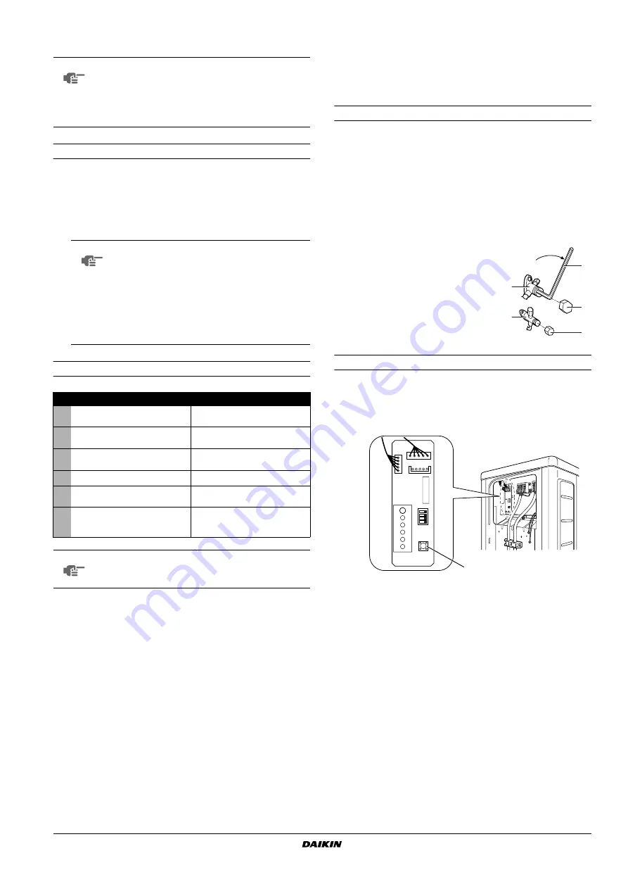
1
Remove the valve lid from liquid stop valve and gas stop valve.
2
Carry out the forced cooling operation.
3
After 5 to 10 minutes (after only 1 or 2 minutes in case of very
low ambient temperatures (<–10°C)), close the liquid stop valve
with a hexagonal wrench.
4
After 2-3 minutes, close the gas stop valve and stop forced
cooling operation.
Forced cooling operation
1
Press the forced operation switch SW1 to begin forced cooling.
2
Press the forced operation switch SW1 again to stop forced
cooling.
D
ISPOSAL
REQUIREMENTS
Dismantling of the unit, treatment of the refrigerant, of oil and of other
parts must be done in accordance with relevant local and national
legislation.
NOTE
Remark that during the first running period of the unit,
required power input may be higher than stated on the
nameplate of the unit. This phenomenon originates
from the compressor that needs elapse of a 50 hours
run in period before reaching smooth operation and
stable power consumption.
NOTE
■
The unit requires a small amount of power in
its standby mode. If the system is not to be
used for some time after installation, shut off
the circuit breaker to eliminate unnecessary
power consumption.
■
If the circuit breaker trips to shut off the
power to the outdoor unit, the system will
restore the original operation mode when the
power supply is restored.
Check
Symptom
■
Outdoor unit is installed properly
on solid base.
Fall, vibration, noise
■
No refrigerant gas leaks.
Incomplete cooling/heating
function
■
Refrigerant gas and liquid pipes
are thermally insulated.
Water leakage
■
System is properly earthed.
Electrical leakage
■
The specified wires are used for
interconnecting wire connections.
Inoperative or burn damage
■
Outdoor unit air intake and
exhaust is free of obstructions.
Stop valves are opened.
Incomplete cooling/heating
function
NOTE
Have the customer actually operate the unit while
looking at the manual included with the indoor unit.
Instruct the customer how to operate the unit correctly.
1
Gas stop valve
2
Close
3
Hexagonal wrench
4
Valve lid
5
Liquid stop valve
1
Forced operation switch SW1
1
3
2
4
4
5
LED-A
SW4
ON
AB
C
D
S102
SW1
S2
1


