Installer reference guide
Daikin Altherma – Low temperature split
English
+
ERHQ011-014-016BAERLQ011-014-016CA16CBV
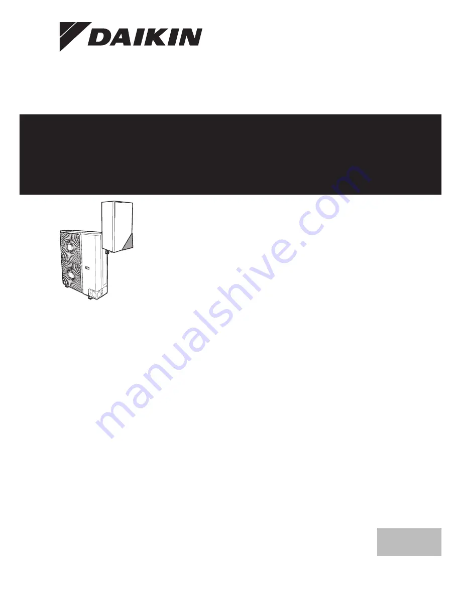
Page 1: ...Installer reference guide Daikin Altherma Low temperature split English Installer reference guide Daikin Altherma Low temperature split ERHQ011 014 016BA ERLQ011 014 016CA EHBH11 16CBV ...
Page 2: ...allation site 23 6 2 1 Installation site requirements of the outdoor unit 23 6 2 2 Additional installation site requirements of the outdoor unit in cold climates 24 6 2 3 Installation site requirements of the indoor unit 24 6 2 4 Installation site requirements of the backup heater 24 6 3 Preparing refrigerant piping 25 6 3 1 Refrigerant piping requirements 25 6 3 2 Refrigerant piping insulation 25...
Page 3: ...r interface 51 8 1 4 To copy the language set from the first to the second user interface 51 8 1 5 Quick wizard Set the system layout after first power ON 51 8 2 Basic configuration 52 8 2 1 Quick wizard Language time and date 52 8 2 2 Quick wizard Standard 52 8 2 3 Quick wizard Options 54 8 2 4 Quick wizard Capacities energy metering 56 8 2 5 Space heating control 56 8 2 6 Domestic hot water cont...
Page 4: ...quate personal protective equipment protective gloves safety glasses when installing maintaining or servicing the system WARNING Tear apart and throw away plastic packaging bags so that nobody especially children can play with them Possible risk suffocation DANGER RISK OF BURNING Do NOT touch the refrigerant piping water piping or internal parts during and immediately after operation It could be t...
Page 5: ...akdown do NOT charge more than the specified amount of refrigerant When the refrigerant system is to be opened refrigerant must be treated according to the applicable legislation WARNING Make sure there is no oxygen in the system Refrigerant may only be charged after performing the leak test and the vacuum drying In case re charge is required refer to the nameplate of the unit It states the type o...
Page 6: ...kage protector make sure it is compatible with the inverter resistant to high frequency electric noise to avoid unnecessary opening of the earth leakage protector NOTICE Precautions when laying power wiring Do not connect wiring of different thicknesses to the power terminal block slack in the power wiring may cause abnormal heat When connecting wiring which is the same thickness do as shown in th...
Page 7: ...nations of units and options Application guidelines Various installation setups of the system Preparation What to do and know before going on site Installation What to do and know to install the system Configuration What to do and know to configure the system after it is installed Commissioning What to do and know to commission the system after it is configured Hand over to the user What to give a...
Page 8: ...autions indoor unit installation manual operation manual and addendum book for optional equipment INFORMATION Do NOT throw away the upper cardboard cover On the outside of the cardboard cover the installation pattern is printed 3 3 2 To remove the accessories from the indoor unit The general safety precautions the indoor unit installation manual the operation manual and the addendum book for optio...
Page 9: ...he outdoor unit Identifying the indoor unit Identifying the backup heater if applicable Combining outdoor and indoor units Combining the outdoor unit with options Combining the indoor unit with options 4 2 Identification NOTICE When installing or servicing several units at the same time make sure NOT to switch the service panels between different models 4 2 1 Identification label Outdoor unit Loca...
Page 10: ...bottom plate Recommended in areas with low ambient temperature and high humidity For ERLQ Bottom plate heater is standard factory mounted For ERHQ Bottom plate heater is option Cannot be combined with drain plug kit If you install EKBPHTH16A you also have to install the digital I O PCB EKRP1HB For installation instructions see the installation manual of the bottom plate heater and addendum book fo...
Page 11: ...tem behaviour For installation instructions see the installation manual of the remote outdoor sensor INFORMATION You can only connect either the remote indoor sensor or the remote outdoor sensor PC configurator EKPCCAB The PC cable makes a connection between the switch box of the indoor unit and a PC It gives the possibility to upload different language files to the user interface and indoor param...
Page 12: ...are clear Daikin recommends to follow the setup guidelines below NOTICE If an external room thermostat is used the external room thermostat will control the room frost protection However the room frost protection is only possible if the leaving water temperature control on the unit s user interface is turned ON INFORMATION In case an external room thermostat is used and room frost protection needs...
Page 13: ... heat pump system Heat pump convectors Setup B A a A Main leaving water temperature zone B One single room a Remote controller of the heat pump convectors The under floor heating or radiators are directly connected to the indoor unit The desired room temperature is set via the remote controller of the heat pump convectors The space heating demand signal is sent to one digital input on the indoor u...
Page 14: ...ain leaving water temperature zone B Room 1 C Room 2 a User interface The under floor heating of the main room is directly connected to the indoor unit The room temperature of the main room is controlled by the user interface used as thermostat A thermostatic valve is installed before the under floor heating in each of the other rooms INFORMATION Mind situations where the main room can be heated b...
Page 15: ...r of the heat pump convectors Combination Under floor heating Heat pump convectors Setup b B C A a M1 A Main leaving water temperature zone B Room 1 C Room 2 a External room thermostat b Remote controller of the heat pump convectors For each room with heat pump convectors The heat pump convectors are directly connected to the indoor unit For each room with under floor heating A shut off valve fiel...
Page 16: ...e Mind that the operation mode on each remote controller of the heat pump convectors must be set to match the indoor unit Configuration Setting Value Unit temperature control A 2 1 7 Code C 07 2 RT control Unit operation is decided based on the ambient temperature of the user interface Note Main room user interface used as room thermostat functionality Other rooms external room thermostat function...
Page 17: ...2 changeover to external heat source on the PCB to the auxiliary boiler thermostat To setup the heat emitters see 5 2 Setting up the space heating system on page 12 Configuration Via the user interface quick wizard Set the use of a bivalent system as external heat source Set the bivalent temperature and hysteresis NOTICE Make sure the bivalent hysteresis has enough differential to prevent frequent...
Page 18: ...k anti legionella heater can increase this temperature However this consumes more energy Daikin recommends to set the desired DHW tank temperature below 55 C to avoid using the electrical resistance The anti legionella heater Is used as emergency heater Is used when the disinfection function for the DHW tank is active Can assist during defrost operation for the outdoor unit The higher the outdoor ...
Page 19: ...For more information about connecting the recirculation connection see 7 Installation on page 29 Configuration For more information see 8 Configuration on page 50 You can program a schedule to control the DHW pump via the user interface For more information see the user reference guide 5 4 6 DHW pump for disinfection Setup c a b d f e g h i a Indoor unit b DHW tank c DHW pump field supply d Heater...
Page 20: ...e and anti legionella heater The voltage Setup and configuration To get accurate energy data measure the capacity resistance measurement and set the capacity via the user interface for The backup heater step 1 and step 2 if applicable The anti legionella heater Measuring the consumed energy Applicable for all models Preferred method because of higher accuracy Requires external power meters Setup a...
Page 21: ...ter L1 L2 L3 N e Fuse L1 N f Fuse L1 L2 L3 N g Outdoor unit L1 N h Indoor unit L1 N i Backup heater L1 L2 L3 N j Anti legionella heater L1 N 5 6 Setting up the power consumption control The power consumption control Is only applicable for EHBH04 08 Allows you to limit the power consumption of the entire system sum of outdoor unit indoor unit anti legionella heater and optional backup heater Config...
Page 22: ...an the electrical heaters Therefore the electrical heaters are limited and turned OFF first The system limits power consumption in the following order 1 Limits certain electrical heaters If has priority Then set the heater priority via the user interface to Domestic hot water production Anti legionella heater Result The backup heater if applicable will be turned OFF first Space heating Backup heat...
Page 23: ...ions chapter Service space requirements See the Technical data chapter Refrigerant piping requirements length height difference See further in this Preparation chapter Select a place where rain can be avoided as much as possible Take care that in the event of a water leak water cannot cause any damage to the installation space and surroundings Do NOT install the unit in the following places Sound ...
Page 24: ... with domestic hot water tank 3 m Maximum distance between the domestic hot water tank and the indoor unit for installations with domestic hot water tank 10 m a Parenthesised figure represents the equivalent length Mind the following spacing installation guidelines 1150 200 200 10 10 500 mm Do NOT install the unit in places such as In places where a mineral oil mist spray or vapour may be present ...
Page 25: ...structions in the Installation chapter respecting the water inlet and outlet Connecting piping Force Do NOT use excessive force when connecting the piping Deformation of the piping can cause malfunctioning of the unit Connecting piping Tools Only use appropriate tooling to handle brass which is a soft material If NOT pipes will get damaged Connecting piping Air moisture dust If air moisture or dus...
Page 26: ...l particles may damage the unit and will NOT be removed by the standard filter of the heat pump system Domestic hot water tank Capacity To avoid stagnation of water it is important that the storage capacity of the domestic hot water tank meets the daily consumption of domestic hot water Domestic hot water tank After installation Immediately after installation the domestic hot water tank must be fl...
Page 27: ... backup heater operation if applicable in the installation is guaranteed in all conditions NOTICE When circulation in each or certain space heating loops is controlled by remotely controlled valves it is important that the minimum flow rate is guaranteed even if all valves are closed In case the minimum flow rate cannot be reached a flow error 7H will be generated no heating operation Minimum requ...
Page 28: ...mpetitive prices and are often authorized to bill clients at benefit rates E g time of use rates seasonal rates Wärmepumpentarif in Germany and Austria This equipment allows for connection to such preferential kWh rate power supply delivery systems Consult with the electricity company acting as provider at the site where this equipment is to be installed to know whether it is appropriate to connec...
Page 29: ...larm output 2 b Item Description Wires Maximum running current 20 Changeover to external heat source control 2 b 21 Space heating operation control 2 b 22 Power consumption digital inputs 2 per input signal b 23 Safety thermostat 2 e a Refer to name plate on outdoor unit b Minimum cable section 0 75 mm c Cable section 2 5 mm d The thermistor and connection wire 12 m are delivered with the domestic...
Page 30: ...nits and or the installation conditions it might be necessary to connect electrical wiring before you can charge refrigerant 7 2 Opening the units 7 2 1 About opening the units At certain times you have to open the unit Example When connecting the refrigerant piping When connecting the electrical wiring When maintaining or servicing the unit DANGER RISK OF ELECTROCUTION Do NOT leave the unit unatt...
Page 31: ...llation structure Check the strength and level of the installation ground so that the unit will not cause any operating vibration or noise Fix the unit securely by means of foundation bolts in accordance with the foundation drawing Prepare 4 sets of anchor bolts nuts and washers field supply as follows mm 150 6 2 0 350 3 4 5 3 5 5 4 M12 a a Make sure not to cover the drain holes INFORMATION The re...
Page 32: ...outdoor unit from falling over In case the unit is installed in places where strong wind can tilt the unit take following measure 1 Prepare 2 cables as indicated in the following illustration field supply 2 Place the 2 cables over the outdoor unit 3 Insert a rubber sheet between the cables and the outdoor unit to prevent the cable from scratching the paint field supply 4 Attach the cable s ends Ti...
Page 33: ...inst the wall 2 1 2 3 2 7 Assemble the unit 1 2 1 2 2 2 3 5 7 4 4 To install the drain pan kit If a drain pan kit EKHBDPCA2 is required install it before connecting the refrigerant and water pipes and the electrical wiring To install see the installation manual of the drain pan kit 7 5 Mounting the backup heater 7 5 1 Precautions when mounting the backup heater INFORMATION Also read the precaution...
Page 34: ... piping from previous installations NEVER install a drier to this R410A unit to guarantee its lifetime The drying material may dissolve and damage the system NOTICE Take the following precautions on refrigerant piping into account Avoid anything but the designated refrigerant to get mixed into the refrigerant cycle e g air Only use R410A when adding refrigerant Only use installation tools e g mani...
Page 35: ...e c Make sure the flare nut is fitted 7 6 6 To braze the pipe end The indoor unit and outdoor unit have flare connections Connect both ends without brazing If brazing should be needed take the following into account When brazing blow through with nitrogen to prevent creation of large quantities of oxidised film on the inside of the piping This film adversely affects valves and compressors in the r...
Page 36: ...e 22 5 27 5 To handle the service cap Always use a charge hose equipped with a valve depressor pin since the service port is a Schrader type valve After handling the service port tighten the service port cap and check for refrigerant leaks Item Tightening torque N m Service port cap 11 5 13 9 7 6 8 To connect the refrigerant piping to the outdoor unit 1 Do the following Remove the service cover a ...
Page 37: ...ndoor unit a b a Refrigerant liquid connection b Refrigerant gas connection 2 Connect the gas stop valve from the outdoor unit to the refrigerant gas connection of the indoor unit NOTICE It is recommended that the refrigerant piping between indoor and outdoor unit is installed in a ducting or the refrigerant piping is wrapped with finishing tape 7 6 10 To determine if oil traps are required If oil...
Page 38: ... the bubble test solution to all connections 3 Discharge all nitrogen gas INFORMATION After opening the stop valve it is possible that the pressure in the refrigerant piping does NOT increase This might be caused by e g the closed state of the expansion valve in the outdoor unit circuit but does NOT present any problem for correct operation of the unit 7 7 5 To perform vacuum drying 1 Vacuum the s...
Page 39: ...igerant piping Setup on page 38 7 8 6 To charge refrigerant WARNING Only use R410A as refrigerant Other substances may cause explosions and accidents R410A contains fluorinated greenhouse gases Its global warming potential GWP value is 2087 5 Do NOT vent these gases into the atmosphere When charging refrigerant always use protective gloves and safety glasses CAUTION To avoid compressor breakdown d...
Page 40: ...nd pressure relief device should be installed on the cold water inlet connection of the domestic hot water cylinder To avoid back siphonage it is recommended to install a non return valve on the water inlet of the domestic hot water tank in accordance with the applicable legislation It is recommended to install a pressure reducing valve on the cold water inlet in accordance with the applicable leg...
Page 41: ...water pump 10 Connecting the alarm output 11 Connecting the space heating ON OFF output 12 Connecting the changeover to an external heat source 13 Connecting the power consumption digital inputs 14 Connecting the safety thermostat 15 Connecting the backup heater if applicable 7 10 2 About electrical compliance ERHQ_V3 Equipment complying with EN IEC 61000 3 12 European International Technical Stan...
Page 42: ... torques Item Tightening torque N m M4 X1M 1 2 1 8 M5 X1M 2 0 3 0 M5 earth 3 0 4 0 7 10 5 Specifications of standard wiring components Component V3 W1 ERHQ ERLQ ERHQ ERLQ Power supply cable MCA a 31 9 A 34 2 A 13 5 A 16 3 A Voltage 230 V 400 V Phase 1 3N Frequency 50 Hz Wire sizes Must comply with applicable legislation Interconnection cable Minimum cable section of 2 5 mm and applicable for 230 V...
Page 43: ... the 3 possibilities a b a b a b 2 3 1 a Power supply earth wiring and bottom plate heater wire if applicable b Interconnection cable Connecting to the frame When cables are routed from the unit a protection sleeve for the conduits PG insertions can be inserted at the knockout hole When you do not use a wire conduit protect the wires with vinyl tubes to prevent the edge of the knockout hole from c...
Page 44: ...utdoor ambient temperature sensor option Indoor ambient temperature sensor option Electrical meters field supply Safety thermostat field supply b High voltage power supply Interconnection cable Normal kWh rate power supply Preferential kWh rate power supply Power supply for anti legionella heater to indoor unit Power supply for anti legionella heater and thermal protection from indoor unit Power s...
Page 45: ... connect the user interface If you use 1 user interface you can install it at the indoor unit for control close to the indoor unit or in the room when used as room thermostat If you use 2 user interfaces you can install 1 user interface at the indoor unit for control close to the indoor unit 1 user interface in the room used as room thermostat The procedure differs slightly depending on where you ...
Page 46: ...l meter with transistor output check the polarity The positive polarity MUST be connected to X5M 7 and X5M 9 the negative polarity to X5M 8 and X5M 10 1 Connect the electrical meters cable to the appropriate terminals as shown in the illustration below X2M X5M 78910 S2S S3S 2 Fix the cable with cable ties to the cable tie mountings 7 10 13 To connect the domestic hot water pump 1 Connect the domes...
Page 47: ...he safety thermostat normal closed cable to the appropriate terminals as shown in the illustration below 3 4 X5M 2 Fix the cable with cable ties to the cable tie mountings INFORMATION After it is installed do NOT forget to configure the safety thermostat Without configuration the indoor unit will ignore the safety thermostat contact INFORMATION The preferential kWh rate power supply contact is con...
Page 48: ...the equipment to ensure by consultation with the distribution network operator if necessary that the equipment is connected only to a supply with a system impedance Zsys less than or equal to Zmax 1 Connect the backup heater power supply A 4 pole fuse is used for F1B 2 If required modify the connection on terminal X14M Backup heater type Connections to backup heater power supply Connections to ter...
Page 49: ...llation 1 Insulate and fix the refrigerant piping and interconnection cable as follows f b a e d c a Gas pipe b Gas pipe insulation c Interconnection cable d Liquid pipe e Liquid pipe insulation f Finishing tape 2 Install the service cover 7 11 2 To close the outdoor unit NOTICE When closing the outdoor unit cover make sure that the tightening torque does NOT exceed 4 1 N m 1 2 1 7 12 Finishing th...
Page 50: ...he PC cable to the switch box Prerequisite The EKPCCAB kit is required 1 Connect the cable with USB connection to your PC 2 Connect the plug of the cable to X10A on A1P of the switch box of the indoor unit A1P X10A 3 Pay special attention to the position of the plug 2 3 4 5 H J S T NOTICE Another cable is already connected to X10A To connect the PC cable to X10A therefore temporarily disconnect th...
Page 51: ...sy and will NOT be possible to operate 3 The quick wizard will guide you 4 For proper operation of the system the local data on the two user interfaces must be the same If this is NOT the case both user interfaces will display Synchronization Data difference detected Please select action Send data Confirm Adjust 5 Select the required action Send data the user interface you are operating contains t...
Page 52: ... shortly turn OFF and busy will be displayed for several seconds 8 2 Basic configuration 8 2 1 Quick wizard Language time and date Code Description A 1 N A Language 1 N A Time and date 8 2 2 Quick wizard Standard Backup heater configuration The optional backup heater is adapted to be connected to most common European electricity grids Besides hardware configuration the grid type and the relay sett...
Page 53: ...ain LWT zone continued Code Description A 2 1 8 7 02 continuation 1 2 LWT zones 2 leaving water temperature zones The zone with the lowest leaving water temperature in heating is called the main leaving water temperature zone The zone with the highest leaving water temperature in heating is called the additional leaving water temperature zone In practice the main leaving water temperature zone con...
Page 54: ...e Description A 2 2 1 E 05 DHW operation Can the system prepare domestic hot water 0 No default NOT installed 1 Yes Installed A 2 2 3 E 07 During domestic hot water preparation the heat pump can be assisted by an electrical heater to ensure the domestic hot water preparation even for high desired tank temperatures DHW tank type 0 Type 1 default Tank with anti legionella heater installed at the sid...
Page 55: ...e must be set See 5 Application guidelines on page 12 1 Thermo ON OFF See Contact type main Connected on the indoor unit X2M 1a 2 H C request default See Contact type main Connected on the indoor unit X2M 1a Code Description A 2 2 B C 08 External sensor When an optional external ambient sensor is connected the type of the sensor must be set See 5 Application guidelines on page 12 0 No default NOT ...
Page 56: ... Description A 2 2 8 D 08 Optional external kWh meter 1 0 No NOT installed 1 Installed 0 1 pulse kWh 2 Installed 1 pulse kWh 3 Installed 10 pulse kWh 4 Installed 100 pulse kWh 5 Installed 1000 pulse kWh A 2 2 9 D 09 Optional external kWh meter 2 0 No NOT installed 1 Installed 0 1 pulse kWh 2 Installed 1 pulse kWh 3 Installed 10 pulse kWh 4 Installed 100 pulse kWh 5 Installed 1000 pulse kWh 8 2 4 Q...
Page 57: ...on the outdoor ambient temperature according a schedule The scheduled actions consists of desired leaving water temperatures either preset or custom Remark This value can only be set in leaving water temperature control Code Description 7 7 1 1 1 00 1 01 1 02 1 03 Set weather dependent heating 1 03 1 02 Ta Tt 1 00 1 01 Tt Target leaving water temperature main Ta Outdoor temperature continued Code ...
Page 58: ... temperatures less warm water is required Leaving water temperature Delta T source Temperature difference for entering and leaving water The unit is designed to support under floor loops operation The recommended leaving water temperature set by the user interface for under floor loops is 35 C In such case the unit will be controlled to realize a temperature difference of 5 C which means that the ...
Page 59: ...m modulation of the desired leaving water temperature Therefore it is important to set this correctly Code Description A 3 1 1 7 9 0B Emitter type Reaction time of the system Quick Example Small water volume and fan coils Slow Example Large water volume floor heating loops 8 2 6 Domestic hot water control Only applicable in case an optional domestic hot water tank is installed Configuring the desi...
Page 60: ...erature ranges all desired leaving water temperatures are also adjusted to guarantee they are between the limits Always balance between the desired leaving water temperature with the desired room temperature and or the capacity according to the design and selection of the heat emitters The desired leaving water temperature is the result of several settings preset values shift values weather depend...
Page 61: ... temperature hysteresis ONLY applicable in case of room thermostat control The hysteresis band around the desired room temperature is settable It is recommended NOT to change the room temperature hysteresis as it is set for an optimal use of the system 9 0C a b c d a Room temperature b Actual room temperature c Desired room temperature d Time Code Description N A 9 0C 1 C 6 C default 1 C Room temp...
Page 62: ...rmostat is Thermo ON then room frost protection is guaranteed by the normal logic In case of then the following applies Two leaving water temperature zones When the leaving water temperature home page is OFF and the outdoor ambient temperature drops below 4 C then the unit will supply leaving water to the heat emitters to heat up the room again and the leaving water temperature setpoint will be lo...
Page 63: ...scription 7 4 3 3 6 0C 30 C min 50 6 0E C default 45 C Reheat hysteresis Only applicable when domestic hot water preparation is scheduled reheat Code Description N A 6 08 2 C 20 C default 10 C Weather dependent The weather dependent installer settings define the parameters for the weather dependent operation of the unit When weather dependent operation is active the desired tank temperature is det...
Page 64: ... domestic hot water The actual anti recycling time also depends on setting 8 04 Range 0 10 hours default 3 step 0 5 hour Remark The minimum time is 1 2 hour even when the selected value is 0 Code Description N A 8 03 Anti legionella heater delay timer Only for EKHW Start up delay time for the anti legionella heater when domestic hot water mode is active When domestic hot water mode is NOT active t...
Page 65: ...alue selected in field setting 2 03 after a disinfection operation When the high domestic hot water temperature can be a potential risk for human injuries a mixing valve field supply shall be installed at the hot water outlet connection of the domestic hot water tank This mixing valve shall secure that the hot water temperature at the hot water tap never rise above a set maximum value This maximum...
Page 66: ...f the house is unattended for longer periods we recommend to set A 6 C Emergency to Automatic Code Description A 6 C N A Emergency 0 Manual default 1 Automatic INFORMATION If 4 03 1 or 3 then Emergency Manual is not applicable for the anti legionella heater INFORMATION The auto emergency setting can be set in the menu structure of the user interface only INFORMATION If a heat pump failure occurs a...
Page 67: ...bserve all rules mentioned in application guideline 5 when bivalent operation function is enabled Daikin shall NOT be held liable for any damage resulting from failure to observe this rule INFORMATION The combination of setting 4 03 0 2 with bivalent operation at low outdoor temperature can result in domestic hot water shortage The bivalent operation function has no impact on the domestic water he...
Page 68: ...s of the type that power supply is interrupted always enable the auto restart function Continuous indoor unit control can be guaranteed independent of the preferential kWh rate power supply status by connecting the indoor unit to a normal kWh rate power supply Code Description A 6 1 3 00 Is the auto restart function of the unit allowed 0 No 1 default Yes Preferential kWh rate power supply INFORMAT...
Page 69: ...setting E 08 needs to be enabled on the user interface in combination with the removal of the power saving connector at the outdoor unit NOTICE The power saving connector at the outdoor unit shall only be removed when the main power supply to the application is switched OFF In case of ERLQ004 008CAV3 3 1 2 3 Code Description N A E 08 Power saving function for outdoor unit 0 Disabled 1 default Enab...
Page 70: ...the priority of the electrical heaters depending on applicable limitation Average timer The average timer corrects the influence of ambient temperature variations The weather dependent set point calculation is done on the average outdoor temperature The outdoor temperature is averaged over the selected time period Code Description A 6 4 1 0A Outdoor average timer 0 No averaging default 1 12 hours ...
Page 71: ...range of the minimum flow error 7H Code Description N A 9 0D Pump speed limitation 0 No limitation 1 4 General limitation There is limitation in all conditions The required delta T control and comfort are NOT guaranteed 5 8 default 6 Limitation when no actuators When there is no heating output the pump speed limitation is applicable When there is heating output the pump speed is only determined by...
Page 72: ...eration modes Running hours Version Energy metering Consumed elec Produced energy Error information Error history Contact helpdesk number Version User interface Indoor unit Outdoor unit User settings Display Temperature lock Set schedules Preset values Allowed operation mode Unit of measurement Display Contrast Backlit LCD time User profile Available home pages Set schedules Room temp LWT main LWT...
Page 73: ... heater steps Forced off contact Unit control method Number of LWT zones Pump operation mode Power saving possible User interface location Options DHW operation Contact type main Contact type add Digital I O PCB Demand PCB External kWh meter External kWh meter DHW pump External sensor Leaving water Main Additional Delta T source Room thermostat Room temp range Room temp offset Ext room sensor offs...
Page 74: ...ler and the local supply panel only applicable in case of hybrid system There are NO missing phases or reversed phases The system is properly earthed and the earth terminals are tightened The fuses or locally installed protection devices are installed according to this document and have not been bypassed The power supply voltage matches the voltage on the identification label of the unit There are...
Page 75: ...ting or the domestic hot water heating mode Typical workflow Purging the air from the system should consist of 1 Performing a manual air purge 2 Performing an automatic air purge INFORMATION Start by performing a manual air purge When almost all the air is removed perform an automatic air purge If necessary repeat performing the automatic air purge until you are sure that all air is removed from t...
Page 76: ...f the pump will start Prerequisite Make sure that the leaving water temperature home page room temperature home page and domestic hot water home page are turned OFF 1 Set the user permission level to Installer See To set the user permission level to Installer on page 50 2 Make sure the room temperature control the leaving water temperature control and the domestic hot water control are turned OFF ...
Page 77: ...election If a time is selected you can set the duration between 1 and 72 hours If a temperature is selected you can set the desired leaving water temperature between 15 C and 55 C 4 To add a new step select h or on an empty line and press 5 To delete a step set the duration to by pressing 6 Press to save the schedule It is important that there is no empty step in the program The schedule will stop...
Page 78: ...ation Formula to calculate the greenhouse gas emissions GWP value of the refrigerant Total refrigerant charge in kg 1000 11 1 Overview Maintenance and service This chapter contains information about The yearly maintenance of the outdoor unit The yearly maintenance of the indoor unit 11 2 Maintenance safety precautions DANGER RISK OF ELECTROCUTION DANGER RISK OF BURNING NOTICE Risk of electrostatic...
Page 79: ...immerse in a bucket or similar with lime removing product for 24 hours 12 Troubleshooting 12 1 Overview Troubleshooting This chapter describes what you have to do in case of problems It contains information about Solving problems based on symptoms Solving problems based on error codes Before troubleshooting Carry out a thorough visual inspection of the unit and look for obvious defects such as loo...
Page 80: ...cal connections do NOT match This should match with the connections as explained in 6 5 Preparing electrical wiring on page 28 and 7 10 9 To connect the main power supply on page 44 The preferential kWh rate signal was sent by the electricity company Wait for the power to return 2 hours max 12 3 3 Symptom The pump is making noise cavitation Possible causes Corrective action There is air in the sys...
Page 81: ... blocked pressure relief valve Flush and clean the complete tank including the piping between pressure relief valve and the cold water inlet Replace the pressure relief valve 12 3 8 Symptom Decoration panels are pushed away due to a swollen tank Possible causes Corrective action Failing or blocked pressure relief valve Contact your local dealer 12 3 9 Symptom Tank disinfection function is NOT comp...
Page 82: ...wer reset required Please contact your dealer A1 01 EEPROM reading error AA 01 Backup heater overheated Power reset required Please contact your dealer AC 00 Booster heater overheated Please contact your dealer Error code Detailed error code Description AH 00 Tank disinfection function not completed correctly AJ 03 Too long DHW heat up time required C0 00 Flow sensor switch malfunction Please cont...
Page 83: ...ating circuit Additionally this error code might be an indication of frost damage to the plate heat exchanger In that case contact your local dealer INFORMATION Error AJ 03 is reset automatically from the moment there is a normal tank heat up INFORMATION Error EC 04 is reset automatically from the moment the domestic hot water tank is preheated to a sufficiently high temperature Error code UA 17 T...
Page 84: ...T have to operate 1 Turn ON the main power supply switch 2 Make sure the liquid stop valve and the gas stop valve are open 3 Press the pump down button BS4 for at least 8 seconds BS4 is located on the PCB in the outdoor unit see wiring diagram Result The compressor and outdoor unit fan start automatically 4 Once operation stops after 3 5 minutes close the liquid stop valve and the gas stop valve R...
Page 85: ...U 200 1000 1000 500 HD HU HU a b 300 300 c d e eB eD A B C D E HB HD A B C 200 300 1000 A B C E 200 300 1000 1000 500 D 1000 D E 1000 1000 500 B D HB HD HB HD 300 1000 HD HU 250 1500 HU HD HU 300 1500 B D E HB HD HB HU 300 1000 1000 500 HU HB HU 300 1250 1000 500 HB HU HB HD HD HU 250 1500 1000 500 HU HD HU 300 1500 1000 500 HD HU ERHQ A B C D Obstacles walls baffle plates E Obstacle roof a b c d ...
Page 86: ... HU 300 1000 1000 500 HD HU ERLQ A B C D Obstacles walls baffle plates E Obstacle roof a b c d e Minimum service space between the unit and obstacles A B C D and E eB Maximum distance between the unit and the edge of obstacle E in the direction of obstacle B eD Maximum distance between the unit and the edge of obstacle E in the direction of obstacle D HU Height of the unit HB HD Height of obstacle...
Page 87: ...ort 5 16 d Accumulator e Filter f Heat exchanger g Internal service port 5 16 h Capillary tube E1HC Crankcase heater M1C Motor compressor M1F M2F Motor upper and lower fan R1T Thermistor air R2T Thermistor discharge R3T Thermistor suction R4T Thermistor heat exchanger R5T Thermistor heat exchanger middle R6T Thermistor liquid S1NPH Pressure sensor S1PH High pressure switch Y1E Electronic expansion...
Page 88: ... Refrigerant side C Field installed a1 Space heating water IN a2 Space heating water OUT b1 Refrigerant IN b2 Refrigerant OUT c Plate heat exchanger d Shut off valve with drain fill valve e Pump f Safety valve g Manometer h Expansion vessel i Flow sensor j Filter R1T Thermistor heat exchanger water OUT R3T Thermistor liquid refrigerant R4T Thermistor heat exchanger water IN Screw connection Flare ...
Page 89: ...heater F1U F8U ERHQ_V3 ERLQ_V3 F1U F3U F4U Fuse T 6 3 A 250 V F6U Fuse T 5 0 A 250 V F7U F8U Fuse F 1 0 A 250 V F1U F9U ERHQ_W1 ERLQ_W1 F1U F2U Fuse 31 5 A 500 V F3U F6U Fuse T 6 3 A 250 V F7U Fuse T 5 0 A 250 V F8U F9U Fuse F 1 0 A 250 V H1P H7P A2P ERHQ_V3 ERLQ_V3 Light emitting diode service monitor orange H2P Prepare test Flickering Malfunction detection Light up H1P H7P A1P ERHQ_W1 ERLQ_W1 Li...
Page 90: ...bipolar transistor IGBT X1M Terminal strip power supply X1Y Connector option for ERHQ bottom plate heater X6A Connector option X77A ERHQ_W1 ERLQ_W1 Connector option Y1E Expansion valve main Y3E ERLQ Expansion valve injection Y1S Solenoid valve 4 way valve Y3S ERHQ_W1 Solenoid valve injection Y3S ERLQ Solenoid valve hot gas pass Z1C Z9C Noise filter Z1F Z4F Noise filter ...
Page 91: ...tat wireless On OFF thermostat wireless Ext thermistor External thermistor Heat pump convector Heat pump convector Position in switch box English Translation Position in switch box Position in switch box Legend A1P Main PCB A2P User interface PCB A3P Solar pump station PCB A3P On OFF thermostat PC power circuit A3P Heat pump convector A4P Digital I O PCB A4P Receiver PCB Wireless On OFF thermostat...
Page 92: ... supply For For For or For or SWB Switch box 6 Optional BUH 6 Optional backup heater SWB Switch box English Translation 7 Anti legionella heater power supply 7 Anti legionella heater power supply For For 8 Option PCBs 8 Option PCBs Alarm output Alarm output Changeover to ext heat source Changeover to external heat source For digital I O PCB option For digital I O PCB option For solar pump station ...
Page 93: ... HYC 400 V 2 earth for EHVH Power supply Anti legionella heater power supply 2 4 kW 230 V earth 3 core F2B L N earth F2B L1 L2 earth Domestic hot water tank 2 core signal 2 core Only for KRCS01 1 or EKRSCA1 signal signal 2 core 2 core 2 core 2 core 2 core signal M2S shut off valve 2 way valve Heating On OFF output Electricity meter pulse input 1 Electricity meter pulse input 2 Only for KSR3PA opti...
Page 94: ...ing on model PCB Optional backup heater configuration only for EKLBUHCB6W1 Optional backup heater configuration only for EKLBUHCB6W1 1N 230 V 6 kW 1N 230 V 6 kW 3N 400 V 6 kW 3N 400 V 6 kW Position in switch box English Translation Position in switch box Position in switch box Legend E1H Backup heater element 1 kW E2H Backup heater element 2 kW F1B Overcurrent fuse backup heater F1T Thermal fuse b...
Page 95: ...090625 1A A External static pressure B Water flow rate C Operation range Operation area is extended to lower flow rates only in case the unit operates with heat pump only Not in startup no backup heater operation no defrost operation ESP External static pressure kPa in the space heating cooling circuit Flow Water flow through the unit in the space heating cooling circuit Notes Selecting a flow out...
Page 96: ...the required service to the product Installation manual Instruction manual specified for a certain product or application explaining how to install configure and maintain it Operation manual Instruction manual specified for a certain product or application explaining how to operate it Accessories Labels manuals information sheets and equipment that are delivered with the product and that need to b...
Page 97: ... Field settings table Applicable indoor units EHBH04CBV EHBH08CBV EHBH11CBV EHBH16CBV EHVH04S18CBV EHVH08S18CBV EHVH08S26CBV EHVH11S26CBV EHVH16S26CBV Notes 1 EHBH 2 EHVH 3 04 08 4 11 16 4P449974 1 2016 06 ...
Page 98: ...C step 1 C 35 C 7 7 2 1 0 01 Set weather dependent heating Leaving water value for low ambient temp for LWT add zone heating WD curve R W 9 05 9 06 C step 1 C 45 C 7 7 2 1 0 02 Set weather dependent heating High ambient temp for LWT add zone heating WD curve R W 10 25 C step 1 C 15 C 7 7 2 1 0 03 Set weather dependent heating Low ambient temp for LWT add zone heating WD curve R W 40 5 C step 1 C 1...
Page 99: ... 0 No 1 Yes A 3 1 1 6 1 F 0B Shut off valve Thermo On OFF R W 0 No 1 Yes A 3 1 1 7 9 0B R W 0 Quick 1 Slow Additional A 3 1 2 1 R W 0 Fixed 1 Weather dep 2 Fixed scheduled 3 WD scheduled A 3 1 2 2 1 9 05 Temperature range Minimum temp heating R W 15 37 C step 1 C 25 C A 3 1 2 2 2 9 06 Temperature range Maximum temp heating R W 37 depending on outdoor unit step 1 C 55 C Delta T source A 3 1 3 1 9 0...
Page 100: ...20 kW A 6 3 5 1 5 05 Amp limits for DI Limit DI1 R W 0 50 A step 1 A 50 A A 6 3 5 2 5 06 Amp limits for DI Limit DI2 R W 0 50 A step 1 A 50 A A 6 3 5 3 5 07 Amp limits for DI Limit DI3 R W 0 50 A step 1 A 50 A A 6 3 5 4 5 08 Amp limits for DI Limit DI4 R W 0 50 A step 1 A 50 A A 6 3 6 1 5 09 kW limits for DI Limit DI1 R W 0 20 kW step 0 5 kW 20 kW A 6 3 6 2 5 0A kW limits for DI Limit DI2 R W 0 20...
Page 101: ...W 0 No 1 Yes A 8 5 00 R W 0 Allowed 1 Not allowed A 8 5 01 R W 15 35 C step 1 C 0 C Do not change this value Below which outdoor temperature is heating allowed Is the installer on site Leaving water value for high ambient temp for DHW WD curve Leaving water value for low ambient temp for DHW WD curve High ambient temp for DHW WD curve Low ambient temp for DHW WD curve Low ambient temp for LWT main...
Page 102: ...C A 8 9 01 R W 15 37 C step 1 C 25 C A 8 9 02 22 A 8 9 03 5 A 8 9 04 R W 1 4 C step 1 C 1 C A 8 9 05 R W 15 37 C step 1 C 25 C Space heating priority Space heating priority temperature Set point correction for domestic hot water temperature What is the requested limit for DI1 What is the requested limit for DI2 What is the requested limit for DI3 What is the requested limit for DI4 What is the req...
Page 103: ...smp ctrl A 8 D 05 R W 0 Forced off 1 As normal A 8 D 07 R W 0 No 1 Yes A 8 D 08 R W 0 No 1 0 1 pulse kWh 2 1 pulse kWh 3 10 pulse kWh 4 100 pulse kWh 5 1000 pulse kWh A 8 D 09 R W 0 No 1 0 1 pulse kWh 2 1 pulse kWh 3 10 pulse kWh 4 100 pulse kWh 5 1000 pulse kWh A 8 D 0A 0 A 8 D 0B 2 A 8 D 0C R W 0 49 0 A 8 D 0D R W 0 49 0 What is the maximum desired LWT for add zone in heating What is the desired...
Page 104: ...05 0 A 8 F 06 0 A 8 F 09 R W 0 Disabled 1 Enabled A 8 F 0A 0 A 8 F 0B R W 0 No 1 Yes A 8 F 0C 1 A 8 F 0D R W 0 Continuous 1 Sample 2 Request Which type of unit is installed Which type of compressor is installed What is the indoor unit software type What is the number of backup heater steps Is the power saving function available on the outdoor unit What is the low electricity price Do not use Can t...
Page 105: ......
Page 106: ......
Page 107: ......
Page 108: ...4P449970 1 2016 06 Copyright 2016 Daikin ...