background image

12

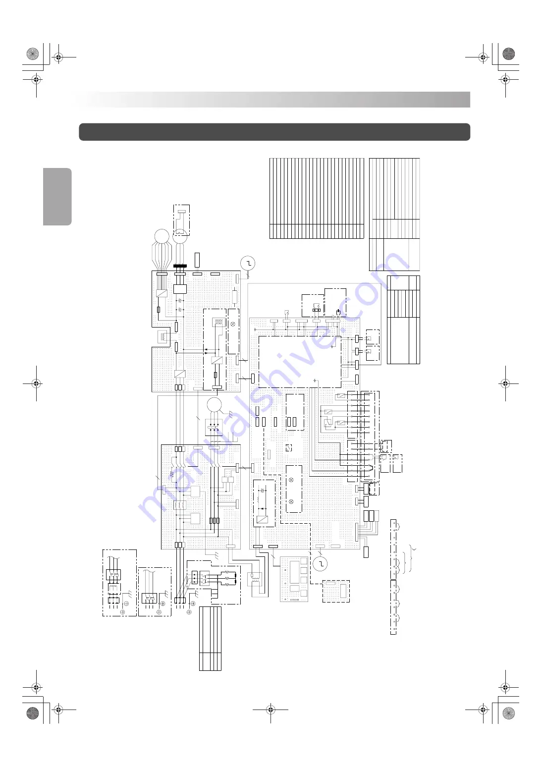
Electric wiring diagram (Typical: AKZ329)

A5P

Additional par

t symbol

Model

Expansion board f

or comm

unication with main machine

Th-9

AKZ9-OP-CS

AKZ9-OP-Y10

AKZ9-OP-Y5

Th-1

Oil temper

ature control ther

mistor

AKZ9-OP-A10

AKZ9-OP-A5

AKZ9-OP-K10

A5P

AKZ9-OP-K5

Machine temper

ature tuning ther

mistor

-047, -048 model only

X3M

Th-1

31

30

13

12

11

10
9

67

66

65

64

63

62

61

60

X3M, X4M

S4T

E1H

"-H" model only

X4M 24

23

S4T

T1R

"-B" model 

MCCB

L2

L3

L1

K2M

MCCB

Circuit breaker

Compressor protection thermostat

High-pressure pressure switch

Temperature fuse

Heater

Magnetic contactor

Magnetic contactor coil

Overheat preventive temperature switch

Oil lack preventive pressure switch

Terminal block

Circuit breaker

Trans

Terminal block

MCCB

-H (Buit-in heater)

-047, -048

-C (CE model)

-B (Built-in break

er model)

(Diff

erent-v

oltage 

model)

Men

u model

Standard, -046 (Diff

erent-v

oltage model)

COR

67

66

65

64

63

62

61

60

Th-6

Th-7

Th-8

S9

T1R

Th-Fin

S3PH

S151

S150

CE model only

Hv

Hu

Vcc

GND

W

V

U

θ

S2T

S172

X2M

9

Alar

m and r

un signals

31

30

13

12

11

10

A4P

Y1E, Y2E

X1M, X2M

Th300

Th-9

Th-6

Th-7

Th-8

Th-1

Th-4

Th-3

DCL

DCL

6.3A 250V

LED300

CN103

-

~

X2M

A4P

A3P

A2P

A1P

Comm

unication

~

+

Th300

Th-Fin

Y1E

Y2E

M2C

M3F

M

IC600

+

~

CN650

X500

M1P

DC

M

3~

M

3~

M

CN14

S0

S160

S90

LED_A

LED140

S10

CN12

Optional par

ts

Th-2

M2C

M3F

S2T

CN, S, X

K1S

M1P

FU

A3P

C

A2P

Alar

m output

ACDC

θ

S2T

S3PH

S172

S171

S170

S179

95

96

K1S

A1P

Th-9

S60

+12V

S140

+12V

+15VE

CN2

S183

S184

S182

S185

31

30

13

12

11

10
9

67

66

65

64

63

62

61

L1

Th-2

Th-3

Th-4

CN11

CN10

S80

S200

CN7

CN6

CN110

CN20

CN18

+

C551

C550

CN15

+

3.15A 250V

FU550

DCL2

DCL1

FU650

3.15A 250V

U1

V1

W1

K1S

T3

T2

T1

L3

L2

60

X530

X510

X520

X519

X501

FU513

FU512

FU511

R

S

T

SA

SA

L3

L2

L1

N=4

X1M

Optional par

ts

S130

CN600

R

S

T

X3M

ST
R

K2M

W2

V2

U2

Black 
Black 
Black

E1H

F1UT

F2UT

K2M

M

5

6

3

2

6

5

2

S5P

F1UT, F2UT

24

4

S5P

X3M

L2

L3

L1

Tr

~

Power supply

3~ 200/200·220V 50/60Hz

Standard, 

-C, 

-B, -T, -H

-046

-047

-048

3~ 220·230V        50/60Hz

3~ 380·400·415V 50/60Hz

3~ 440·460·480V 50/60Hz

Model

Power supply

MR52Pa

MR30Y

MR30X

MR30W

AKZ9-OP-K15

COR

X3M

L2

L3

L1

Tr

Input

Output

0V

MCCB

-047, -048 model only

Black (Red)

Black (White)

Black

Shor

t-circuit bar

Black (Red)

Black (White)

Black

Black (Red)

Black (White)

Black

"-H" model  only

Red

Red

Blac

k

Blac

k

Remote 

control

Optional 

protectiv

de

vice

F

or connection 

of machine 

temper

ature 

tuning 

ther

mistor

Alar

m le

v

el output 

Alar

m/po

w

er f

ailure

Nor

mal  pump r

un

OFF

:Le

v

el1

ON  :Le

v

el2

W

ar

ning output

Optional par

ts

Optional par

ts

"-H" model only

 Note) 1.

 T

o use optional oil temper

ature control ther

mistor (Th-9), substitute it   

for the outlet oil temper

ature ther

mistor (Th-2) on CN11.

2.

 F

or details

, ref

er to the electr

ic wir

ing diag

ram f

or each model.

CE model only

CE model only

Shor

t-circuit 

bar

Shor

t-circuit 

bar

Magnetic 

contactor coil

"-H" model only

Yello

w

Red

White

Blac

k

Bro

wn

Or

ange

Blue

Red

Y

ello

w

Blue

In

ver

ter CPU nor

mal

P

o

w

er supply circuit

Blac

k

Blac

k

Blac

k

Surge  absorber

RELA

Y control

Blac

k (Red)

Blac

k (White)

Blac

k

Photocoupler

RELA

Y control

Base 

comm

unication

Control CPU 

nor

mal

P

o

w

er supply circuit

Expansion 

user I/O

F

or 

comm

unication 

(par

allel)

F

or ser

ial comm

unication

Analog monitor

PR

O

TECT SW 

(erroneous oper

ation 

pre

vention)

F

or shipping adjustment

High-precision 

analog input

Protection de

vice 

input circuit

Optional par

ts

 P

ar

t type

T

ype

Name

Control board

In

v

er

ter board

Noise filter board

Displa

y board

Condenser

Connector

F

err

ite Core

Reactor

Fuse

Ov

er-current rela

y

Mor

tor (pump)

Mor

tor (compressor)

Mor

tor (f

an)

Machine temper

ature tuning ther

mistor (Optional)

Outlet oil temper

ature ther

mistor

Air (room temper

ature) ther

mistor

Inlet oil temper

ature ther

mistor

Exhaust gas temper

ature ther

mistor

Condenser temper

ature ther

mistor

EV v

alv

e outlet temper

ature ther

mistor

Oil temper

ature ther

mistor (Optional)

Fin temper

ature ther

mistor

Control bo

x temper

ature ther

mistor

T

rans

T

er

minal b

loc

k

Electr

ic e

xpansion v

alv

e

Installation

Installation 

Pr

ocedure

PIM00318A_EN.fm  Page 12  Tuesday, October 26, 2010  12:37 PM

Summary of Contents for AKZ149

Page 1: ...ture Control Improvement 30 Alarm Warning Output Logic 33 Alarm Settings for Optional Protection Devices Installed by User 33 Handling Before Operation 13 Model Identification and Specifications 14 Part Names and Functions 15 Names and Functions of the Control Panel Parts 16 Checking Initial Operating Conditions 18 Operation Setting 19 Holding Constant Oil Temperature 20 Tuning Oil Temperature to ...

Page 2: ...PIM00318A_EN fm Page 0 Tuesday October 26 2010 12 37 PM ...

Page 3: ...power cable according to the procedure described in Electric Wiring on page Connect the power cable according to the procedure described in this instruction manual Check the weight of the unit with the nameplate to make sure that it does not exceed the rated load capacity of the carrier Hang the unit by the points specified in the outline drawing Failure to observe this instruction may result in f...

Page 4: ...serve this instruction may result in short circuit or electric shock Do not touch electric components with wet hands Failure to observe this instruction may result in electric shock Do not splash water During this period electric discharge from the internal high voltage parts capacitors has not been completed Failure to observe this instruction may result in electric shock Dot not handle the unit ...

Page 5: ...un or no accident occurs even if the main machine runs Failure to observe this instruction may result in injury or damage to the machine Ensure safety of the main machine before trial run Do not put an obstacle within 500 mm from the air intake exhaust port If air intake exhaust flow is blocked this unit may not provide the specified cooling capacity Do not install a duct at the exhaust port Do no...

Page 6: ...lified personnel after the power supply is turned OFF Installation Installation Procedure Oil Cooling Unit and Accessories Check the following items Some models do not come with accessories Check the model name and serial No MFG No on the nameplate attached to the right side of the Oil Cooling Unit Oil Cooling Unit 1 An accessory package 1 is attached to the top plate of the Oil Cooling Unit Keep ...

Page 7: ...ll 4 For the different voltage model 047 048 carry out the transportation or conveyance using the hanger of transformer box If you hang it using the eye plate it may fall 5 Set the ambient storage temperature to 0 to 55 C annual average 25 C and set the ambient humidity to 95 RH or less annual average is less than 75 Stay away from the product during transportation or conveyance using the hanging ...

Page 8: ...Clean or replace the strainer before starting actual operation Check the strainer periodically The oil pollution level must not exceed NAS class 10 Suction strainer Line filter Attach a strainer mesh size 100 to 150 with a small pressure loss to the oil piping system Oil tank Right side view Rear view OIL OUTLET Exhaust air Intake air OIL DRAIN No connection OIL INLET To receive oil from the main ...

Page 9: ...r general hydraulic oil lubrication oil P Pipe resistance MPa V Kinematic viscosity coefficient mm2 s See Viscosity vs Temperature chart Q Flow rate L min L Pipe length m D Pipe inner diameter mm For flow rate Q refer to Oil pump discharge rate in Model Identification and Specifications on page Oil Inlet Model Connection pipe AKZ149 329 439 Oil Drain Oil Outlet Rc3 4 Rc3 4 Rc1 4 Pipe size maximum ...

Page 10: ... turn ON the power supply for the Oil Cooling Unit the following three methods are available When the circuit breaker for the main machine is turned ON the Oil Cooling Unit starts operation To stop the unit turn OFF the circuit breaker for the main machine Directly starting stopping the Oil Cooling Unit with the main machine power supply Starting stopping the Oil Cooling Unit When the remote contr...

Page 11: ...ire coating Fix the electric wire and the signal wire to the anchor mount with tie wrap See page For remote control input connecting procedure refer to page For external output contact connecting procedure refer to page Use conduits with IP54 or higher for wiring intake to allow the electric component box to have a protective structure equivalent to IP54 If the electric component box is affected b...

Page 12: ...nal block Signal terminal block Anchor mount 9 10 11 13 30 31 12 60 61 62 64 65 66 63 67 Short circuit bar No fuse breaker Over current Relay Controller board CN12 CN2 CN11 Signal terminal block Protect SW 9 10 11 13 30 31 12 60 61 62 64 65 66 63 67 Short circuit bar Over current Relay Controller board Protect SW 9 10 11 12 13 30 31 60 61 62 63 64 65 66 67 380V 400 415 380 400 415 380 400 415 440V...

Page 13: ...rm level Alarm a contact Normal Stop Power OFF b contact Between terminals 60 and 63 Between terminals 60 and 63 Pump run a contact Alarm level Between terminals 60 and 61 LOCK key Between terminals 10 and 11 Between terminals 61 and 62 Between terminals 60 and 64 Between terminals 60 and 61 Between terminals 61 and 62 Between terminals 60 and 64 Preset condition Output logic parameter setting 0 M...

Page 14: ... 200 220V 50 60Hz Standard C B T H 046 047 048 3 220 230V 50 60Hz 3 380 400 415V 50 60Hz 3 440 460 480V 50 60Hz Model Power supply MR52Pa MR30Y MR30X MR30W AKZ9 OP K15 COR X3M L2 L3 L1 Tr Input Output 0V MCCB 047 048 model only Black Red Black White Black Short circuit bar Black Red Black White Black Black Red Black White Black H model only Red Red Black Black Remote control Optional protective de...

Page 15: ...ater Power supply 2 Transformer capacity Exterior color Outer dimensions H W D Compressor Fully enclosed DC swing type Evaporator Condenser Propeller fan Motor Refrigerant control Vertical 14 7 m s2 1 5 G 2 5 hr 10 to 100 Hz sweep 5 min Transportation vibration resistance 10 Required for the models other than B Local procurement item Circuit breaker Rated current Refrigerant New refrigerant R410A ...

Page 16: ...cification list on page of the instruction manual Connect the operation signal of the pump to the signal terminal block referencing the connection of the external output contact on page of the instruction manual For the power supply be sure to observe the order of pump ON and OILCON ON Use the pump complying with the thermal relay setting the current value of the pump Oil piping 3 Check the oil pi...

Page 17: ... produce low temperature low pressure gas refrigerant Limits the oil pump discharge pressure within a specified level A part of the oil piping for suction and discharge of the oil pump 10 11 12 13 14 15 16 17 18 Air filter Oil drain Evaporator Circuit breaker B only High pressure pressure switch C only Compressor protection thermostat C only Heater H only Transformer 047 048 only Oil tank T only L...

Page 18: ... alarm is activated Blinks Operation stops Alarm level 1 Lit Only the compressor stops Alarm level 2 Display the current operation mode NORMAL SETTING or the data number currently displayed on the data display Decrements the number of operation mode or data number value by one If you keep pressing this key the number is decremented by ten Increments the number of operation mode or data number valu...

Page 19: ...NITOR lamp is lit Displays the current value of each thermistor etc 23 page Timer setting mode TIMER lamp is lit Used to set up time for the ON timer 24 page 1 The operation modes marked with a circle can be used for normal operation 2 Parameter means a constant to be defined for each setting Mode changing operation Normally the key is used to shift between individual modes For special modes you c...

Page 20: ...ctory settings may be different from the above Holding constant oil temperature Tuning oil temperature to room temperature or machine temperature Cooling oil at constant capacity Check the indication on the control panel The DAIKIN factory setting is the Operation lock mode 1 You hear tick sound after power ON while the electronic expansion valve is under initial setup This does not mean a fault 2...

Page 21: ...erature Outlet oil temperature Returned oil temperature 2 Inlet oil temperature Outlet oil temperature Returned oil temperature 2 3 p 21 9 p 22 5 p 21 5 p 21 9 9 9 9 K 0 100 9 9 9 9 K 9 9 9 9 K 4 p 21 6 p 21 6 p 21 9 9 9 9 K 9 9 9 9 K 9 9 9 9 K Room temperature None None Machine temperature 2 The oil cooling system of the Oil Cooling Unit is as shown below System outline drawing Description on the...

Page 22: ...de After the number is registered the number on the data display blinks The number on the operation mode display remains lit 3 After changing the number press the key to register it After the temperature setting is registered the number on the operation mode display blinks The number on the data display remains lit 5 After changing the set value press the key to register it When the number on the ...

Page 23: ...ber to 3 4 5 or 6 with the or key 2 Change the operation mode After the number is registered the number on the data display blinks The number on the operation mode display remains lit 3 After changing the number press the key to register it After the temperature setting is registered the number on the operation mode display blinks The number on the data display remains lit 5 After changing the set...

Page 24: ...e After the number is registered the number on the data display blinks 9 on the operation mode display remains lit 3 After changing the number press the key to register it After the temperature setting is registered the number on the operation mode display blinks The number on the data display remains lit 5 After changing the set value press the key to register it When the number on the data displ...

Page 25: ... the thermistor and input output values simultaneously appear on the data display Machine temperature Th1 Outlet oil temperature or returned oil temperature Th2 Room temperature Th3 Inlet oil temperature Th4 Reserve Th5 T Th4 Th2 Capacity command value Compressor inverter rotation speed rps Power consumption kW Status of expansion DIN third digit DOUT second digit Go to the monitor mode with the k...

Page 26: ...r key The unit of set value is h hour 2 Specify an operation start time Press the key to register the timer setting When the timer is activated the Oil Cooling Unit is halted The value on the data display blinks The TIMER lamp red LED blinks Keep the main power supply ON 3 Set up the timer With the built in heater model H the electric heater heats up oil to a preset temperature during main machine...

Page 27: ...y setting Maximum value Minimum value Item Remarks No Communication with main machine Alarm output logic Warning Auto tuning Not used Alarm and warning output logic OP contact level OP2 contact level Outlet oil temperature decrease Auto tuning end condition P I gain calculation coefficient Response coefficient Control gain P for low deviation Control gain I for low deviation Control gain P for hig...

Page 28: ...lue appears 2 Select a parameter number Press the key to register the parameter number After the number is registered the value on the data display blinks P on the data number display remains lit 3 Register the parameter number After the set value is registered the value on the data display remains lit P blinks on the data number display 5 After changing the set value press the key to register it ...

Page 29: ...ction set the corresponding parameters You can specify up to five warning conditions with the following five groups of parameters For temperature range warning the above 1 to 5 types are available Actually however any combinations of these types are enabled The above 1 to 5 types can be simultaneously used 1 When the outlet oil temperature Th2 or inlet oil temperature Th4 is 15 C or lower the comp...

Page 30: ...External output Rely 30 output ON Outlet oil temperature Th2 Inlet oil temperature Th4 Room temperature Th3 Machine temperature Th1 Third digit n010 2 n012 3 n014 4 n016 n010 262 462 n012 255 455 n014 321 141 n016 231 411 1 2 3 1 4 6 2 4 2 4 3 1 2 4 5 2 4 3 1 5 1 2 3 1 4 5 Second digit First digit 1 When the outlet oil temperature Th2 or inlet oil temperature Th4 is 15 C or lower the compressor st...

Page 31: ...ng status will be automatically reset When the outlet oil temperature Th2 or inlet oil temperature Th4 is 35 C or higher the compressor stops FH alarm and the 30W relay output turns ON or OFF When the outlet oil temperature Th2 or inlet oil temperature Th4 is at least 5 C lower than the room temperature Th3 or machine temperature Th1 the 30W relay output turns ON or OFF When the difference between...

Page 32: ...eration mode Note 1 3 Note 4 Note 5 Note 6 After completion T Deviation C T Deviation C T Deviation C Handling Useful Functions ForTemperature Control Improvement Auto tuning mode Outline of the function Depending on the system of the main machine problems of unstable temperature control or slow response in temperature control may be raised In such cases it is possible that the temperature control...

Page 33: ...a and writing gain into each parameter Operation at 0 capacity Stop 6 Completion of auto tuning Operation at 0 capacity Stop Normal mode Normal Normal Normal Normal Original operation mode Keep pressing these keys simultaneously for five seconds Error Cancel Cancel Cancel Cancel Cancel Cancel Cancel Cancel Cancel Operation at 0 capacity Stop Error Operation at 0 capacity Stop Error Operation at 0 ...

Page 34: ...ecrease Auto tuning end condition Setting range 0 0 to 10 0 C Initial value 8 0 C When the outlet oil temperature decreases by the temperature specified in this parameter auto tuning data collection ends If the specified temperature range is too small temperature control gain may not be correctly calculated You should set this parameter to the maximum value in the range where it does not cause dam...

Page 35: ...minals 12 and 13 1 Connect the signal cable of the optional protection device to terminals 12 and 13 on the Oil Cooling Unit signal terminal block See Outline of electrical equipment box on page 2 Set Parameter n002 0 OP terminal is not used Factory setting 1 When OP contact turns OFF Alarm Level 1 is activated 2 When OP contact turns OFF Alarm Level 2 is activated 3 When OP contact is not ON afte...

Page 36: ...No polarity See Outline of electrical equipment box on page Optional Parts Mounting procedure Type Name Dimensions Application Installed by user Compatible model AKZ9 OP K10 AKZ9 OP A5 AKZ9 OP A10 10 m AKZ9 OP K15 15 m 5 m 10 m AKZ9 OP K5 5 m For machine temperature tuning control attached to machine body surface For machine temperature tuning control embedded in machine body AKZ9 series Machine t...

Page 37: ...e Optional parts Mounting procedure Type Lead wire length L m Name Dimensions Application Installed by user Compatible model AKZ9 OP Y10 AKZ9 OP Y5 For returned oil temperature control Mounted to main machine oil piping AKZ9 series Oil temperature control thermistor Oil Cooling Unit Main machine 10 m 5 m Rc 1 8 Screw seat Oil piping Connection to control board connector CN11 of Oil Cooling Unit Su...

Page 38: ... the main machine Optional parts Type Communication method Mounting position Compatible model Specification No AKZ9 OP CS Serial communication only AKZ149 AKZ329 AKZ439 Sheet Metal PSP04664 Mounting procedure AKZ9 OP CS To main machine or PC Signal terminal block Over current Relay Power supply terminal block Connection to CN12 on Oil Cooling Unit control board via supplied lead wire CN1 CN2 AKZ9 ...

Page 39: ...nds and push it up while warping it forward Condenser See page Check whether there are any substances in the condenser by removing the air filter You do not need to remove the external plate If the condenser becomes extremely dirty clean it with a brush air blower etc When cleaning the condenser fins wear gloves Otherwise you may be injured by the sharp edges However do not use water or cleaning a...

Page 40: ...pipe connection is loose 2 The suction strainer is clogged 3 The oil level in the oil tank has decreased 1 The compressor is stopped under temperature control 5 The capacity setting is 0 Mode 9 1 There is an obstacle near the air intake exhaust port 2 The air filter is clogged 3 The unit is running under capacity suppressing control because the room temperature is high 1 The alarm output signal co...

Page 41: ...at blocks ventilation at 500 mm or shorter distance from the air intake exhaust port Do not place any object that blocks ventilation at 500 mm or shorter distance from the air intake exhaust port Check if the power supply voltage is not lower than the specified operating range Check for an instantaneous power supply voltage drop at startup of peripheral equipment If the unit is properly installed ...

Page 42: ... refill refrigerant Exchange any phase of the power supply wiring Contact DAIKIN Contact Center Replace the control board Make sure that any phase is properly connected to the power supply terminal block Check the condition detected with the relevant protection device Make sure that the slave communication line is properly connected This error occurs only when the slave does not make response in m...

Page 43: ...warning 2 2E Temperature range warning 3 3E Temperature range warning 4 4E 5E Check the preset warning condition 1 The monitor temperature has exceeded the preset temperature It does not mean a fault of the Oil Cooling Unit 1 The discharge pipe temperature thermis tor is disconnected or short circuited The system will be stopped to protect OIL CON by upgrading the state to an alarm after operation...

Page 44: ...achinery into which it is to be incorporated has been declared in conformity with the provisions of the Machinery and their amendments Note This declaration becomes invalid if technical or operational modifications are introduced without the manufacturer s consent 05 Also complies with the provisions of the following European Directives EMC Directive 2004 108 EC Relevant information that should be...

Page 45: ...PIM00318A_EN fm Page 43 Tuesday October 26 2010 12 37 PM ...

Page 46: ...PIM00318A_EN fm Page 44 Tuesday October 26 2010 12 37 PM ...

Page 47: ...PIM00318A_EN fm Page 45 Tuesday October 26 2010 12 37 PM ...

Page 48: ...uipment Osaka Office 1 1 NISHIHITOTSUYA SETTSU SHI OSAKA 566 8585 JAPAN TEL 81 6 6349 4475 FAX 81 6 6349 7682 Home Page http www daikinpmc com PIM00318A FS 1010 PIM00318A_EN fm Page 46 Tuesday October 26 2010 12 37 PM ...

Reviews: