background image

10

English

5. 

Pressure test and evacuating system

WARNING

• 

Make sure that air or any matter other than refrigerant (R410A) does not get into the refrigeration cycle.

• 

If refrigerant gas leaks should occur, ventilate the room as soon and as much as possible.

• 

R410A, as well as other refrigerants, should always be recovered and never be released directly into the environment.

•  Use a vacuum pump for R410A exclusively. Using the same vacuum pump for different refrigerants may damage the vacuum 

pump or the unit.

CAUTION

It is highly recommended that you do not open/close the stop valves when the outdoor temperature is below −5°F (−21°C) as 

this may result in refrigerant leakage.

• 

When piping work is complete, it is necessary to perform a pressure test 
and evacuate system with a vacuum pump.

• 

If using additional refrigerant, perform air purging from the refrigerant 
pipes and indoor unit using a vacuum pump, then charge additional 
refrigerant.

•  Use a hexagonal wrench (3/16 inch (4mm)) to operate the stop valve rods

.

• 

All refrigerant pipe joints should be tightened with a torque wrench to the 

specified tightening torque.
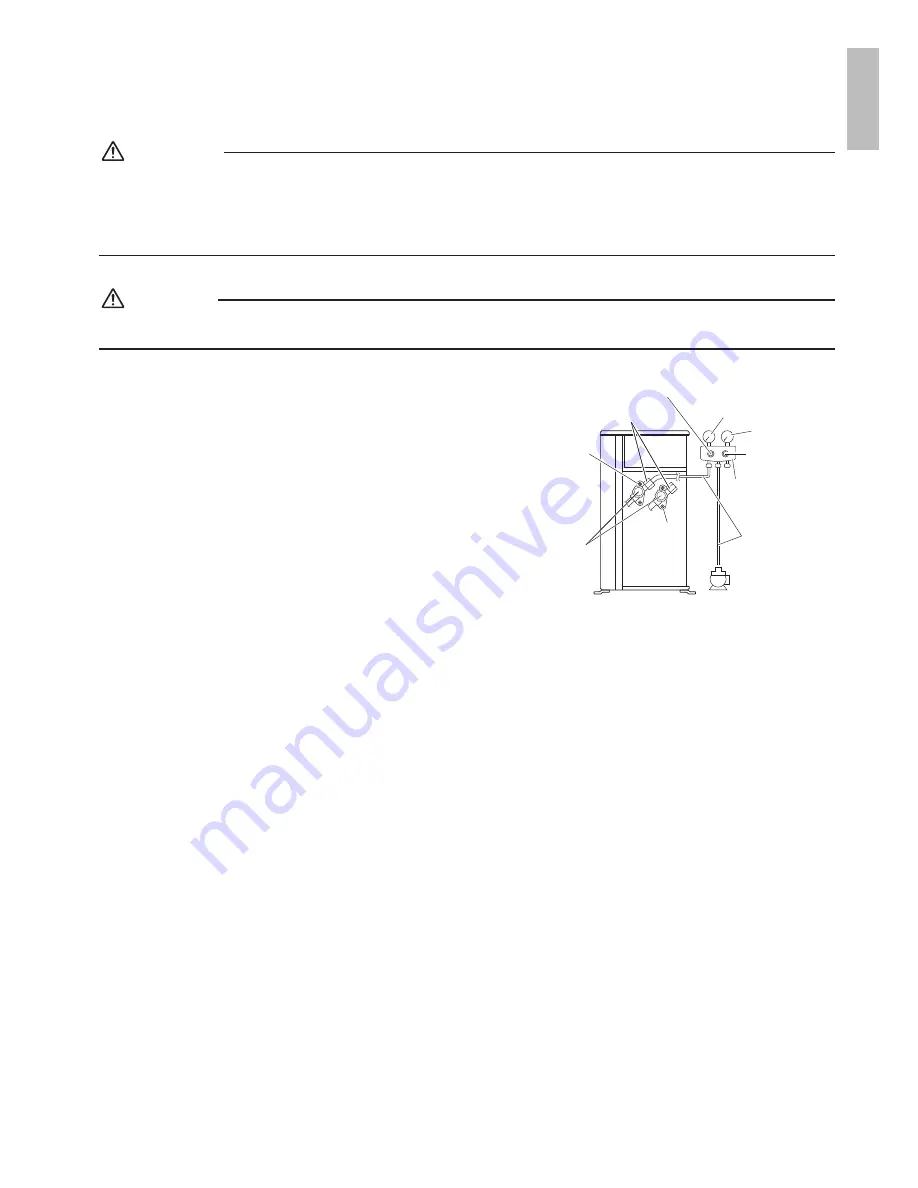
Compound 

pressure gauge

Pressure meter

High-pressure 

valve

Low-pressure valve

Vacuum

pump

Gas 

stop 

valve

Charging 

hoses

Gauge 

manifold

Service port

Liquid 

stop 

valve

Valve 

caps

1) Pressurize the liquid pipe and gas pipe from the service ports of each stop valve to 550psi (3.8MPa) (do not pressurize 

more than 550psi (3.8MPa)) for 1 hour minimum, 24 hours recommended. If there is a pressure drop, check for leaks, 
make repairs and perform the pressure test again. 

2) Connect the gauge manifold’s charging hose to the gas stop valve’s service port.
3) Fully open the low-pressure valve (Lo) on the gauge manifold and fully close the high-pressure valve (Hi). 

(High-pressure valve will require no further operation.)

4) 

Evacuate system using vacuum pump to below 500 microns for 1 hour minimum.

5) Close the low-pressure valve (Lo) on the gauge manifold and stop vacuum pump. 

(Maintain this condition for 4-5 minutes to make sure that the compound pressure gauge pointer does not swing back.)*

1

6) Remove the valve caps from the liquid stop value and gas stop valve.
7) 

To open the liquid stop valve, turn the rod of the valve 90° counter-clockwise using a hexagonal wrench.


Close it after 5 seconds, and check for gas leakage. 

Using soapy water, check for gas leakage from the indoor unit’s flare and outdoor unit’s flare and valve rods.


After the check is complete, wipe all soapy water off.

8) Disconnect the charging hoses from the service port for the gas stop valve, then fully open the liquid and gas stop valves. 

(Do not attempt to turn the valve rods further than they can go.)

9) 

Tighten the valve caps and service port caps for the liquid and gas stop valves with a torque wrench to the specified 

torques. 
Refer to 

“4. Refrigerant piping”

 on page 9 for details.

*

1

  If the compound pressure gauge pointer swings back, the refrigerant may have water content or there may be a loose 

pipe joint. 
Check all pipe joints and retighten nuts as needed, then repeat steps 3) through 5).

English

01_EN_3P537039-1.indd   10

9/12/2018   7:37:44 PM

Summary of Contents for 4MXL36TVJU

Page 1: ...nglish Français Español MODELS 5MXS48TVJU 4MXL36TVJU DAIKIN ROOM AIR CONDITIONER INSTALLATION MANUAL R410A Split Series Installation manual Manuel dinstallation Manual de instalación Manuel dinstallation ...

Page 2: ...ssive leak can lead to oxygen depletion especially in basements and an asphyxiation hazard could occur leading to serious injury or death Do not ground units to water pipes gas pipes telephone wires or lightning rods as incomplete grounding can cause a severe shock hazard resulting in severe injury or death Additionally grounding to gas pipes could cause a gas leak and potential explosion causing ...

Page 3: ...m getting into the system b Tight R410A does not contain any chlorine does not destroy the ozone layer and does not reduce the earth s protection again harmful ultraviolet radiation R410A can contribute to the greenhouse effect if it is released Therefore take proper measures to check for the tightness of the refrigerant piping installation Read the chapter Refrigerant Piping Work and follow the p...

Page 4: ...ife of the air conditioner 8 Since water will flow from the drain of the outdoor unit do not place under the unit anything which must be kept away from moisture NOTE Cannot be installed suspended from a ceiling or stacked CAUTION When operating the air conditioner in a low outdoor ambient temperature be sure to follow the instructions described below To prevent exposure to wind install the outdoor...

Page 5: ...ndoor units 9 13 16 250 from wall Allow space for piping and electrical servicing If there is a danger of the unit falling or overturning fix the unit with foundation bolts or with wire or other means In sites with poor drainage use block bases for the outdoor unit Adjust foot height until the unit is level Otherwise water leakage or pooling of water may occur Also insulate the connection on the ou...

Page 6: ...hange the orientation of the outdoor unit outlet side or use the air direction adjustment grille sold separately More than 3 15 16 100 More than 13 3 4 350 Selecting a Location for Installation of the Indoor Units The maximum allowable length of refrigerant piping and the maximum allowable height difference between the outdoor and indoor units are listed below The shorter the refrigerant piping th...

Page 7: ...ng size is determined by the size of the indoor unit fittings Reducers are used at the outdoor unit to accommodate the correct gas line pipe size 4MXL36 Port B 07 09 12 15 18 D E 07 09 12 15 18 24 A 07 09 12 C 07 09 12 15 18 Use a reducer to connect pipes Use No 2 and 4 reducers Use No 5 and 6 reducers Use No 1 and 3 reducers 5MXS48 07 09 12 15 18 07 09 12 15 18 24 07 09 12 07 09 12 15 18 07 09 12...

Page 8: ... inch 12 7mm Be sure to attach the gasket No 2 φ1 2 φ3 8 No 3 φ5 8 φ1 2 No 4 φ1 2 φ3 8 No 5 φ5 8 φ3 8 No 6 φ5 8 φ3 8 Connection port of outdoor unit No 5 No 6 Flare nut for φ3 8 inch 9 5mm Be sure to attach the gasket When using the reducer packing shown above be careful not to overtighten the nut or the smaller pipe may become damaged Apply about 2 3 to 3 3 the normal torque Apply a coat of refri...

Page 9: ...ends in the hose if it is too long or hangs down 5 Make sure the D drain plugs and the B drain socket of the outdoor unit are securely inserted and there is no leakage Drain plugs D Drain plugs Air outlet side B Drain socket D C Drain socket cap B Drain socket Projection Projection 3 Flaring the pipe end WARNING Do not use mineral oil on flared part Prevent mineral oil from getting into the system...

Page 10: ...15 3 8ft lbf 17 0 21 0N m 7 8 inch 22mm 16 1 4 19 7 8ft lbf 22 0 27 0N m Cautions on pipe handling Protect the open end of the pipe from dust and moisture All pipe bends should be as gentle as possible Use a pipe bender for bending Wall If no flare cap is available cover the flare mouth with tape to keep dirt and water out Be sure to place a cap Rain Selection of copper and heat insulation materials...

Page 11: ...Pa for 1 hour minimum 24 hours recommended If there is a pressure drop check for leaks make repairs and perform the pressure test again 2 Connect the gauge manifold s charging hose to the gas stop valve s service port 3 Fully open the low pressure valve Lo on the gauge manifold and fully close the high pressure valve Hi High pressure valve will require no further operation 4 Evacuate system using ...

Page 12: ...phon pipe inside so the cylinder need not be upside down to fill with liquid Filling other cylinders Turn the cylinder upside down when filling Be sure to use the R410A tools to ensure pressure and to prevent foreign objects entering 7 Charging with refrigerant CAUTION Even though the stop valve is fully closed the refrigerant may slowly leak out do not leave the flare nut removed for a long period ...

Page 13: ...er with at least 1 8 inch 3mm between the contact point gaps When carrying out wiring take care not to pull at the conduit Do not connect the power wire to the indoor unit Doing so may cause electric shock or fire Do not turn on the circuit breaker until all work is completed Method of Mounting Conduit When connecting indoor units for 3 rooms or more open knockout holes without deforming the condu...

Page 14: ...om D terminal blocks are actually integrated Recommend using AWG14 stranded and insulated wire for connections between indoor and outdoor units Local code always supersedes recommendation Shape the wires so that there is no lifting of the shield cover or other structural parts For Room A For Room E For Room C For Room D For Room B For power supply Ground wires Ground wires Use the specified wires a...

Page 15: ...ording to the operation mode of the set indoor unit 2 Priority during powerful operation If the indoor unit which is set for priority room setting is operating at powerful the capabilities of other indoor units will be somewhat reduced Power supply gives priority to the indoor unit which is set for priority room setting 3 Quiet operation priority Setting the indoor unit to quiet operation will mak...

Page 16: ...edure Turn the night quiet mode switch SW6 1 to on COOL HEAT mode lock S15 1 Remove the top plate 10 screws 2 Remove the right side plate 6 screws 3 Remove the front plate 1 screw The front plate is heavy so take care 4 Remove the shield plate 2 screws 5 Use the S15 connector to set the unit to only cool or heat Setting to only heat H short circuit pins 1 and 3 of the connector S15 Setting to only...

Page 17: ...ervice PC board switch cover 1 screw 4 Switch SW5 and SW6 to off 5 Turn the operation mode switch SW2 to COOL 6 Screw the service PC board switch cover back on 1 screw 7 Attach the shield cover 2 screws and the right side plate 6 screws 8 Turn on the power 9 Push the forced operation switch SW1 above the service PC board cover The operation will start Forced cooling operation will stop automatical...

Page 18: ...er to the collective indications label on the reverse side of the right side plate or the service manual If self correction is not possible check the indoor unit wiring and piping in the usual manner Service PC board A 1 2 3 4 5 Wiring error check switch SW3 LED Status 1 2 3 4 5 All Flashing Automatic correction impossible Automatic correction completed Abnormal stop Note 3 Message Flashing One af...

Page 19: ... unit inlet and outlet If the measurements are above the values shown in the table below then they are normal COOL operation HEAT operation Temperature difference between inlet and outlet About 14 F 8 C About 36 F 20 C When running in one room 2 5 After trial operation is complete set the temperature to a normal level 78 F to 82 F 26 C to 28 C in COOL operation 68 F to 75 F 20 C to 24 C in HEAT op...

Page 20: ...Two dimensional bar code is a manufacturing code 3P537039 1 M18B063 1809 HT ...

Reviews: