50
AGZ 025D through 190D
OMM 1087-1
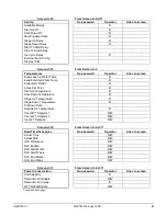
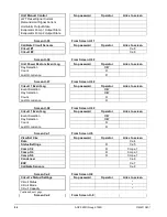
Screen U-11
From Screen U-1
Commission Unit
No password
Operator
Links to screen
Modbus Setup
U-21
AWM Setup
U-22
Ctrlr IP Setup
U-24
Alarm Active
U-30
Alarm Log
U-31
Scheduled Maintenance
U-8
Manual Control Unit
U-34
Manual Control Circuit 1
Cx-3
Manual Control Circuit 2
Cx-3
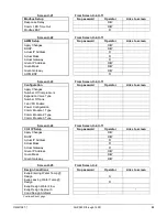
Screen U-12
From Screen U-1, U11
About Chiller
No password
Operator
Links to screen
Model Number
R
R
G. O. Number
R
R
Unit Serial Number
R
R
BSP Version
R
R
Application Version
R
R
HMI GUID
R
R
OBH GUID
R
R
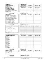
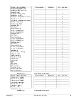
Screen U-13
From Screen U-4
Status/Settings
No password
Operator
Links to screen
Unit Status
R
Next Compressor On
R
Next Compressor Off
R
Chiller Enable
R
Control Source
R
Chiller Enable Setpoint – Network
R
Chiller Mode Setpoint – Network
R
Cool Setpoint – Network
R
Capacity Limit Setpoint – Network
R
Stage Up Delay Remaining
R
Stage Down Delay Remaining
R
Clear Stage Delays
R/W
Ice Setpoint – Network
R
Ice Cycle Time Remaining
R
Clear Ice Cycle Delay
Evap Pump Control
Evap Recirculate Timer
Evap Nominal Delta T
Evap Pump 1 Run Hours
R
Evap Pump 2 Run Hours
R
Remote Service Enable
R
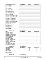
Continued next page.
Summary of Contents for AGZ-D 25
Page 12: ...12 AGZ 025D through 190D OMM 1087 1 Figure 2 Typical Field Control Wiring...
Page 71: ......
Page 81: ......
Page 83: ......


