background image


Interface  Operation    60 
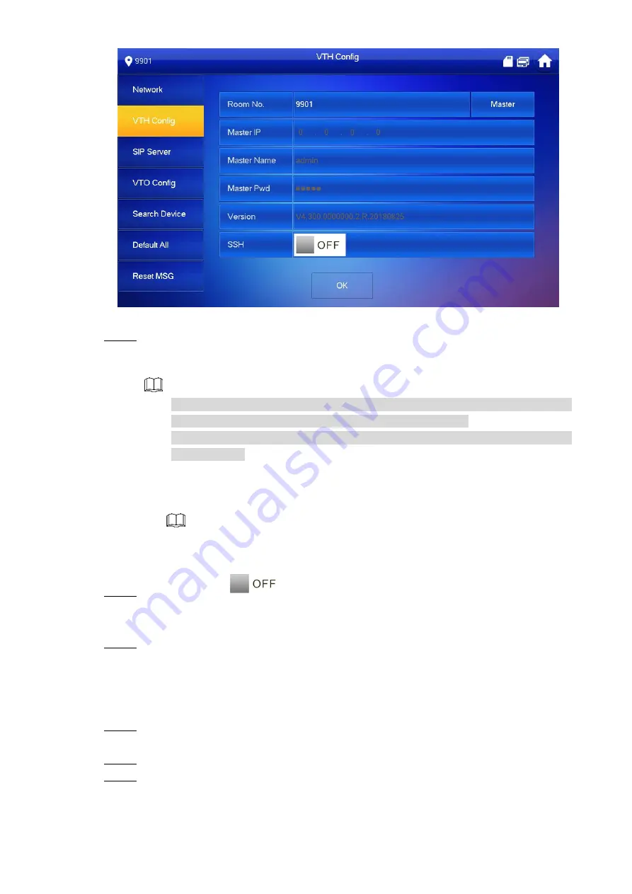
Figure 6-24 

  Set VTH info. 

Step 4


Be used as a master VTH. 

Enter 

“Room No.” (such as 9901 or 101#0). 


“Room no.” shall be the same with  “VTH Short No.”, which is set when adding 
VTH at WEB interface. Otherwise, it will fail to connect VTO. 


In  case  of  extension  VTH,  room  no.  shall  end  with  #0.  Otherwise,  it  will  fail  to 

connect VTO.   


Be used as an extension VTH. 

1)  Press [Master] and switch to 

“Extension”. 

2)  Enter 

“Room No.” (such as 101#1) and “Master IP” (IP address of master VTH). 


“User Name” and “Password” are the user name and password of master VTH. 
Default user name is admin, and the password is the one set during initialization. 

  (Optional) press 

to enable SSH. 

Step 5

After SSH is enabled, the debugging terminal connects VTH through SSH protocol, so 

as to operate and debug it. 

  Press [OK] to save settings.   

Step 6

6.3.4 VTO Config 

Add VTO and fence station info, and bind VTH with VTO on the VTH side. 

  Press [Setting] for over 6 seconds.   

Step 1

The system pops up 

“Password” prompt box. 

  Enter the password set during initialization, and press [OK]. 

Step 2

  Press [VTO Config]. 

Step 3

The system displays 

“VTO Config” interface, as shown in Figure 6-25. 

Summary of Contents for VTH5221 series

Page 1: ...Digital VTH User s Manual V1 2 0...

Page 2: ...CH VTH1520CH VTH1550CH VTH1550CHM VTH16 series VTH1660CH VTH2X series VTH2221A 2 wire VTH VTH1550CHW 2 VTH5222CH Device Upgrade Please don t cut off power supply during upgrade Power can be cut off on...

Page 3: ...subject to change without prior written notice The product updates might cause some differences between the actual product and the manual Please contact the customer service for the latest program an...

Page 4: ...t drip or splash liquids onto the device don t put on the device anything filled with liquids in order to prevent liquids from flowing into the device Please install the device at well ventilated pla...

Page 5: ...3 VTH15 Series Type A Type B Type CH 9 2 2 4 VTH5222CH VTH5222CHW 2 10 2 2 5 VTH1660CH 10 2 2 6 VTH2221A 11 3 Network Diagram 12 2 wire System 12 3 1 Digital System 12 3 2 4 Device Installation 15 Ins...

Page 6: ...6 4 4 Call from VTO 67 6 4 5 Recent Call 69 Monitor 70 6 5 6 5 1 Monitoring of VTO 70 6 5 2 Monitoring of IPC 72 6 5 3 Favorite 75 SOS 76 6 6 Info 76 6 7 6 7 1 Security Alarm 76 6 7 2 Guest Message 7...

Page 7: ...lize talk Monitoring Monitor fence station VTO and IPC devices SOS Press the key to call the Call Center in case of an emergency Auto Snapshot Snapshot the call picture or monitoring picture and store...

Page 8: ...Microphone Voice input 4 Display screen 7 type D digital VTH owns a 7 high definition LCD 10 type D digital VTH owns a 10 high definition LCD 5 Unlock Press this key during calling talking monitoring...

Page 9: ...with handset They are the same except appearance color as shown in Figure 2 2 and Figure 2 3 Figure 2 2 No Name Description 1 Display screen 7 high definition LCD 2 Microphone Voice input 3 Indicator...

Page 10: ...cy Menu Press this key to return to main menu Call In case of incoming call press this key to answer the call During talk press this key to hang up During monitoring press this key to speak to apartme...

Page 11: ...nabled For DND settings please refer to 6 2 2 DND Settings Table 2 4 Figure 2 5 VTH15 Series Type B Icon Name Description SOS Press this key to call the Call Center in case of emergency Menu Press thi...

Page 12: ...ng and speaking of VTO so corresponding VTO will be unlocked Message indicator If this indicator turns on it represents that there are unread messages Power indicator If this indicator turns on in gre...

Page 13: ...to apartment VTO villa VTO and fence station During speaking press this key to exit speaking Monitor In standby mode press this key to monitor the main VTO During monitoring press this key to exit mo...

Page 14: ...to monitor the main VTO During monitoring press this key to exit monitoring Unlock Press this key during calling talking monitoring and speaking of VTO so corresponding VTO will be unlocked Power indi...

Page 15: ...ction VTH5221E H VTH5221EW H front panels are shown in Figure 2 10 Figure 2 10 2 2 3 VTH15 Series Type A Type B Type CH In VTH15 series different types of digital VTH have different port positions but...

Page 16: ...5222CHW 2 Except different numbers of 2 wire port VTH5222CH and VTH5222CHW 2 are the same in other aspects VTH5222CH has 1 group of 2 wire port while VTH1550CHW 2 has 3 groups of 2 wire port VTH5222CH...

Page 17: ...Product Structure 11 Figure 2 15 2 2 6 VTH2221A VTH2221A provides 8 ch alarm input ports 1 ch network port and power port as shown in Figure 2 14 Figure 2 14...

Page 18: ...k Diagram 2 wire System 3 1 Network diagram of 2 wire system is shown in Figure 3 1 Figure 3 1 Digital System 3 2 Digital system network consist of two types VTH adopts PoE power supply from floor swi...

Page 19: ...Network Diagram 13 Figure 3 2 VTH adopts independent power supply from power supply device as shown in Figure 3 3...

Page 20: ...Network Diagram 14 Figure 3 3...

Page 21: ...o 4 4 Device Installation Open case Inspection 4 2 Please carry out open case inspection when receiving the device Please timely contact our after sales service personnel in case of any problems Seque...

Page 22: ...osive and direct sunshine environment Engineering installation and debugging shall be done by professional teams Please don t dismantle or repair arbitrarily in case of device failure Device Installat...

Page 23: ...Step 1 Fix installation bracket onto 86 box with screws Step 2 Put the device into installation bracket from top down Step 3 Figure 4 3 4 4 3 Desktop Installation with Bracket Install the device with...

Page 24: ...reference to Figure 2 10 Step 2 After wiring guide the wire through wire outlet in the rear or at the bottom of desktop Step 3 bracket Put the handset VTH along slot at the top of metal bracket and i...

Page 25: ...be used with VTO of SIP system This manual introduces Unit VTO as an example Please refer to matched user s manuals for other types of VTO Set VTO info and VTH info at WEB interface of every VTO set V...

Page 26: ...o login WEB interface It shall be at least 8 characters and shall include at least two types of number letter and symbol Figure 5 2 Select Email and enter your Email address This Email address is used...

Page 27: ...user name and password and click Login Step 7 Log in the WEB interface of the device Default user name is admin Password is the one set during initialization 5 1 1 2 Network Config Modify IP address o...

Page 28: ...WEB interface again 5 1 1 3 Set System Type Default system type is analogue system and shall be changed to TCP IP Otherwise it will fail to connect VTH successfully Select Local Setting Basic Step 1 T...

Page 29: ...ings or multiple units 5 1 1 5 SIP Server Config Configure SIP server info Select Network Setting SIP Server Step 1 The system displays SIP Server interface as shown in Figure 5 8 Figure 5 8 Configure...

Page 30: ...o login interface Parameter Description IP Address IP address of the platform Port It is 5080 by default Username Use default value Password SIP Domain SIP domain can be null or default SIP Server Use...

Page 31: ...em Adopt default value IP Address IP address of VTO Username Username and password to login WEB interface of this VTO Password Table 5 3 Click OK to complete adding Step 5 Repeat these steps to add ot...

Page 32: ...e system displays Room No Management interface as shown in Figure 5 11 Figure 5 11 Click Add Step 2 The system displays Add interface as shown in Figure 5 12 Figure 5 12 Set VTH parameters by referenc...

Page 33: ...hort no shall end with 1 2 and 3 For example if master VTH is 101 0 extensions will be 101 1 101 2 Register Password Signaling interactive use in SIP system Adopt default value Register Type Table 5 4...

Page 34: ...work According to available network connection modes configure VTH network information IP addresses of VTH and VTO shall be in the same network segment Otherwise VTH will fail to obtain VTO info after...

Page 35: ...ork Figure 5 15 Figure 5 16 Set according to actual network access mode Step 4 LAN Enter Local IP Subnet Mask and Gateway press OK Or press to enable DHCP function and obtain IP info automatically If...

Page 36: ...k Wireless IP tab press to enable DHCP function and obtain IP info automatically as shown in Figure 5 18 To obtain IP info with DHCP function use a router with DHCP function Figure 5 18 5 1 2 3 VTH Co...

Page 37: ...101 1 and Master IP IP address of master VTH Master Name and Master Pwd are the user name and password of master VTH Default user name is admin and the password is the one set during device initializ...

Page 38: ...ver server IP is IP address of the VTO Network Port When the platform works as SIP server network port is 5080 When VTO works as SIP server network port is 5060 User Name Use default value Register Pw...

Page 39: ...n domain of SIP server shall be VDP User Name User name and password to login SIP server Login Pwd Table 5 6 Set Enable Status to be Step 5 Enable SIP server function Press OK to save config Step 6 5...

Page 40: ...e Status to be Press to turn page and add more sub VTO fence stations Debugging Verification 5 2 5 2 1 VTO Calls VTH Dial VTH room no such as 101 at VTO and thus call VTH VTH pops up monitoring image...

Page 41: ...shown in Figure 5 23 Select the VTO to enter monitoring image as shown in Figure 5 24 The following figure means that SD card has been inserted into VTH If SD card is not inserted recording and snaps...

Page 42: ...will be displayed View delete and clear videos and pictures 4 Status Bar Wired network connection icon meaning that the device isn t connected with network Wired network connection icon meaning that t...

Page 43: ...Table 6 1 Table 6 2 Figure 6 1 No Name Description 1 Room No Number of the room where VTH is located 2 Call Call a user Manage the contacts View and manage the call records 3 Info View delete and clea...

Page 44: ...It is not enabled by default 5 Time Display date day of the week and time 6 Arm disarm Display the last unread alarm info press this icon to enter arm mode selection 7 Setting Press Setting input log...

Page 45: ...assword is 123456 Please refer to 6 2 6 3 Password Setting for details Select Ring VTO Ring Setup Step 3 The system displays VTO Ring Setup interface as shown in Figure 6 2 Press or to page up and dow...

Page 46: ...and to set the volume Step 4 6 2 1 3 Alarm Ring Set the ring when VTH gives an alarm Press Setting Step 1 The system pops up Password prompt box Input login password and press OK Step 2 Default login...

Page 47: ...ute setting VTO Ring Time and VTH Ring Time of extension VTH are synchronized with master VTH and cannot be set Press Setting Step 1 The system pops up Password prompt box Input login password and pre...

Page 48: ...function is not enabled by default Under DND mode there is no call reminder when VTH is called but call info is recorded Parameters at this interface are set on master VTH only and extension VTH sync...

Page 49: ...es Step 4 The system displays DND period as shown in Figure 6 7 Figure 6 7 Press time text box set start time and end time Step 5 Press Click to select week and select DND week Step 6 Press OK to save...

Page 50: ...t Alarm Wire Zone Step 3 The system displays Wire Zone interface as shown in Figure 6 8 Figure 6 8 Press corresponding positions to set area type NO NC alarm status enter delay and Step 4 exit delay P...

Page 51: ...armed area within the delay time period will not lead to linkage alarm Linkage alarm will be produced if delay time comes to an end and it is not disarmed Delay is only valid to the areas of delay al...

Page 52: ...to Table 6 3 for details Press Edit to select a zone and press Delete to delete the selected area 6 2 3 3 Alarm Output After enabling alarm output when other devices call this VTH the alarm output dev...

Page 53: ...status under different modes Area mode can be set only in disarm status Press Setting Step 1 The system pops up Password prompt box Input login password and press OK Step 2 Default login password is 1...

Page 54: ...t modes 6 2 5 Forward Setting Forward incoming calls Parameters at this interface are set on master VTH only and extension VTH synchronizes with master VTH Press Setting Step 1 The system pops up Pass...

Page 55: ...swer the incoming call will be deemed as busy forwarding No Answer If no one answers after VTH ring time the incoming call will be forwarded to preset number Set VTH ring time at Setting Ring Other in...

Page 56: ...system displays Time interface as shown in Figure 6 13 Figure 6 13 Set time parameter Step 4 When system time switch is obtain server time by default when it is set system time time zone and DST manu...

Page 57: ...DST start time and end time 6 2 6 2 Display Setting Set VTH screen brightness screensaver time and clean Press Setting Step 1 The system pops up Password prompt box Input login password and press OK...

Page 58: ...d and anti hijacking password of VTH setting interface Login password arm disarm password and unlock password are 123456 by default whereas anti hijacking password is the reversed login password Param...

Page 59: ...esident to resident call time auto capture and touch ring Extension VTH can set Auto Capture and Touch Ring but other parameters synchronize with master VTH and cannot be set Press Setting Step 1 The...

Page 60: ...VTO calls enter message status according to prompt and upload the message to FTP server If VTH doesn t have SD card and VTO has not enabled Leave Message Upload if VTH doesn t answer when VTO calls ha...

Page 61: ...fo Reboot the system and format SD card If SD card isn t inserted into the device SD format function is invalid Press Setting Step 1 The system pops up Password prompt box Input login password and pre...

Page 62: ...interface as shown in Figure 6 19 Figure 6 19 Scan the QR code with any code scanning APP bind your email box send it by email Step 3 to support_cpwd htmicrochip com and thus obtain security code Pres...

Page 63: ...the same network segment Otherwise VTH will fail to obtain VTO info after configuration Press Setting for over 6 seconds Step 1 The system pops up Password prompt box Enter the password set during in...

Page 64: ...LAN Enter Local IP Subnet Mask and Gateway manually press OK Or press to enable DHCP function and obtain IP info automatically If the device has wireless function please click LAN tab to set it WLAN...

Page 65: ...automatically as shown in Figure 6 23 To obtain IP info with DHCP function use a router with DHCP function Figure 6 23 6 3 3 VTH Config Configure VTH info VTH Room No shall be the same with VTH Short...

Page 66: ...master VTH User Name and Password are the user name and password of master VTH Default user name is admin and the password is the one set during initialization Optional press to enable SSH Step 5 Afte...

Page 67: ...e station name IP address User Name and Password 2 Switch the Enable Status to be Press to add more sub VTOs fence stations 6 3 5 Default All parameters of the device except IP address can be restored...

Page 68: ...3 The system displays Reset MSG interface as shown in Figure 6 26 Figure 6 26 Enter New Email and press OK Step 4 The Email will obtain security code during password resetting For details please refer...

Page 69: ...Figure 6 27 6 4 1 1 Add User Press Add Step 1 The system displays User Info interface as shown in Figure 6 28 Figure 6 28 Enter Last Name First Name and Room No of contact person Step 2 Press OK to c...

Page 70: ...se refer to 6 2 6 4 Other Settings for details Call function is used by VTH to call VTH If both VTHs have a camera bilateral video call can be provided 6 4 2 1 Dial and Call User directly At Call User...

Page 71: ...101 1 please enter room no 1 if the extension calls master VTH please enter room no 0 Press to start Step 3 The system displays calling interface as shown in Figure 6 30 After the user answers the ca...

Page 72: ...Please add contact persons to the contact by reference to 6 4 1 1 Add User Select Call Contact Step 1 Select the one you want to call Step 2 Press to start Step 3 6 4 3 Call from User When another VTH...

Page 73: ...as shown in Figure 6 33 For key description please refer to Table 6 6 Press to hang up Figure 6 33 6 4 4 Call from VTO Dial VTH room no such as 9901 at VTO to call VTH Step 1 VTH pops up a waiting pic...

Page 74: ...device Press this key to prohibit talking press it again to switch back to talking status Press this key to select IPC in Favorite that shall be monitored Press this key to snapshot This key is gray...

Page 75: ...Select Call Recent Call and the system displays Recent Call interface In case of missed call press on the front panel and enter recent call interface Figure 6 35 6 4 5 1 Callback Select the recent ca...

Page 76: ...pick up the call automatically Select Monitor VTO Step 1 The system displays the list of added VTO and fence station as shown in Figure 6 36 Press to add frequently used VTO or fence station to favor...

Page 77: ...rd of this VTH If SD card is full the earlier videos will be covered This key is gray if SD card is not installed If VTH connects multiple VTO IPC press and to switch to last next channel Press this k...

Page 78: ...VTO IPC press and to switch to last next channel Press this key to cancel monitoring Press this key to speak to the other end device Press this key to start and the icon becomes Press it again to com...

Page 79: ...camera parameters Step 3 Parameter Description IPC Press this key to select IPC NVR DVR and HCVR Select IPC meaning that VTH obtains video stream from the connected IPC directly It is necessary to con...

Page 80: ...rotocol Please select according to the protocol of the connected device Channel If IPC is connected default setting is 1 If NVR XVR HCVR is connected set channel number of IPC on NVR XVR HCVR Table 6...

Page 81: ...e monitor the VTO by reference to Table 6 8 Step 3 6 5 3 Favorite Display VTO fence stations or IPC that have been added to favorites To view favorite list please ensure that VTO fence station or IPC...

Page 82: ...management center has been connected Otherwise it will fail to call In emergency press button on the front panel or press SOS at the main interface to call management center Info 6 7 6 7 1 Security A...

Page 83: ...6 43 All tab displays all alarm info of the system whereas Unread tab displays unread alarm info Press Edit to select the info press Delete to delete the selected info Press Clear to delete all recor...

Page 84: ...messages Press Edit to select the info press Delete to delete the selected info Press Clear to delete all messages after confirmation Figure 6 44 6 7 3 Publish Info Info released by the management ce...

Page 85: ...s valid All videos and pictures are stored in SD card Select Info Video Pictures and the system displays Video Pictures interface as shown in Figure 6 46 Press Edit to select the video or picture pres...

Page 86: ...and Disarm Function 6 9 6 9 1 Arm In case of triggering alarm after arm produce linkage alarm and upload alarm info Please ensure that the area has been added into arm mode Otherwise there will be no...

Page 87: ...d of exit delay time 6 9 2 Disarm Please ensure that it is in armed status Otherwise disarm will fail Press disarm symbol at the lower right corner of the main interface Step 1 The system displays pas...

Page 88: ...ly connected On the VTH main interface tap Setting Step 1 The Password Verification dialog box is displayed Figure 7 1 Input the password you configured and then select General QR Code Step 2 The Regi...

Page 89: ...DSS Mobile for VDP 83 Figure 7 3 Tap and then scan the Register code on the VTH See Step 2 in 7 1 Step 2 Downloading the App The IP address and port number of your DSS server is displayed...

Page 90: ...DSS Mobile for VDP 84 Figure 7 4 Tap Confirm then Input the user name and password you need and then tap Step 3 Registration You can register 5 users on a VTH at most...

Page 91: ...DSS Mobile for VDP 85 Figure 7 5 Tap Login Step 4 The Login interface is displayed Input the user name and password you registered and then tap Login Step 5 The Call Records interface is displayed...

Page 92: ...DSS Mobile for VDP 86 Figure 7 6...

Page 93: ...l forward on the VTH If any device is calling the VTH you will receive the call on the phone Log in the app and then tap Setting Step 1 The Settings interface is displayed and the SIP ID here is 3 1 1...

Page 94: ...orwarded In the input box behind the forward type you need input the SIP code Step 4 If you want to forward the calls to a specific user input the SIP code of that user For example if you input 3 1 10...

Page 95: ...ward is properly configured you can receive and answer phone calls from the VTO or the management center When the VTO is making video call you can answer the call and unlock the door remotely Figure 7...

Page 96: ...DSS Mobile for VDP 90 Figure 7 11...

Page 97: ...tor voice communication and unlock Log in the app and then tap Monitor Step 1 The Monitor interface is displayed Figure 7 12 You can tap Call Manager to call the management center Tap the sign and the...

Page 98: ...DSS Mobile for VDP 92 Figure 7 13 Tap Open Door to unlock the door Tap Speaking to do voice communication with the VTO...

Page 99: ...ard you can view the call records from the VTO or the management center Log in the app and then Tap Call Records Step 1 The Call Records interface is displayed Figure 7 14 You can view the missed call...

Page 100: ...DSS Mobile for VDP 94 Message 7 6 Log in the app and then tap Message Step 1 The Message interface is displayed You can view the access messages and alarm messages Figure 7 14...

Page 101: ...DSS Mobile for VDP 95 Figure 7 15 You need to enable event subscription first See 7 7 Setting...

Page 102: ...the function you need and then it changes to Step 2 Enable Event Subscription and then you can view the access messages and alarm messages See 7 6 Message Enable Sound and then the phone rings when r...

Page 103: ...heck for updates function to obtain timely information of firmware updates released by the manufacturer We suggest that you download and use the latest version of client software Nice to have recommen...

Page 104: ...Choose TLS to access mailbox server FTP Choose SFTP and set up strong passwords AP hotspot Choose WPA2 PSK encryption mode and set up strong passwords 11 Audio and Video Encrypted Transmission If you...

Page 105: ...99 use VLAN network GAP and other technologies to partition the network so as to achieve the network isolation effect Establish the 802 1x access authentication system to reduce the risk of unauthoriz...

Reviews: