Dahua Villa VTO Quick Start Manual Download Page 27


19 


Click “OK”. 

3.

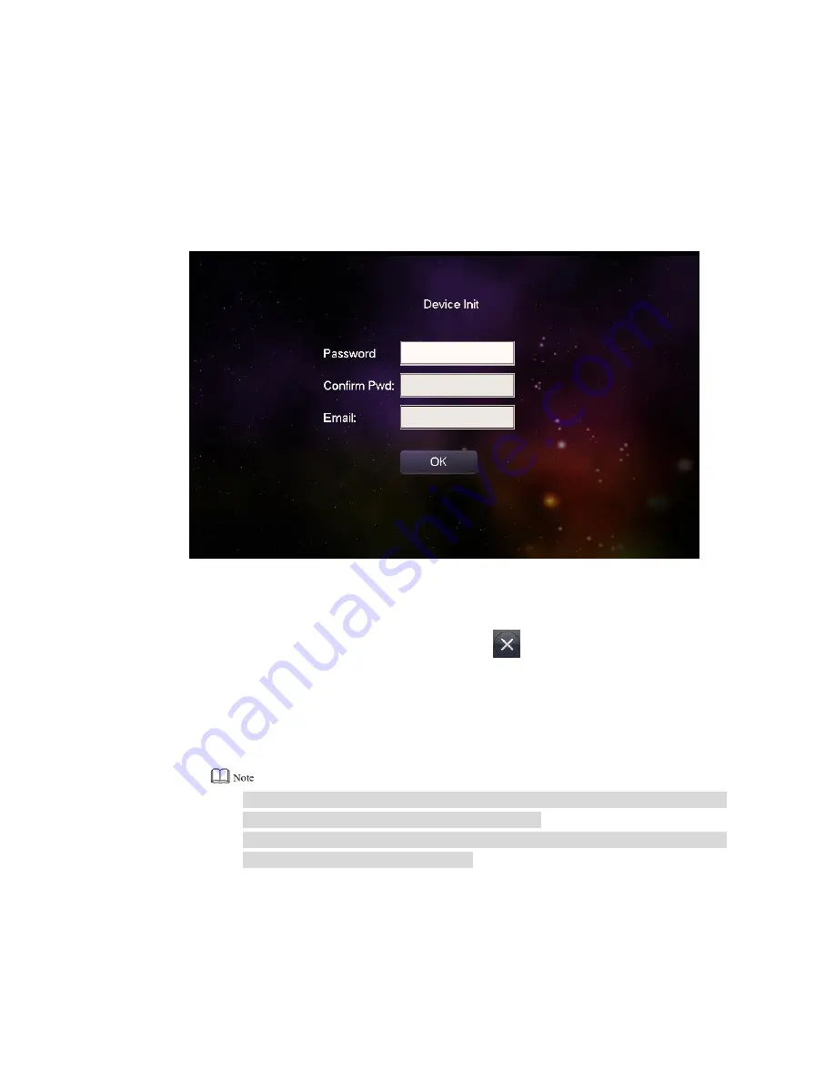
2.2.2 VTH Settings (Version 3.1) 

For  the  first  time,  please  initialize  the  password  and  bind  Email.  Password  is  used  to  enter 

project setting interface, while Email is used to retrieve your password when you forget it. 

  Power on the device. 

Step 1

The system displays “Welcome” and enters “Initialization” interface, as shown in Figure 
2-11. 


Figure 2-11 


Enter “Password”, “Confirm Pwd” and “Email”.   

Step 2

  Click [OK]. 

Step 3

The system displays “Info Init” interface. Press 

  to turn it off. 


Select “System Config >Project Settings”. 

Step 4

The system pops up “Password” prompt box. 

  Enter the password set during initialization, and click [OK]. 

Step 5

  Click [Net Set]. 

Step 6

The system displays “Net Set” interface, as shown in Figure 2-12. 


IP addresses of VTH and VTO shall be in the same network segment. Otherwise, 

VTH will fail to obtain VTO info after configuration. 


To obtain IP with DHCP, please ensure the connected router has DHCP function 

and DHCP function has been enabled. 

Summary of Contents for Villa VTO

Page 1: ...Villa VTO Version 3 1 Quick Start Guide V1 0 1...

Page 2: ...the credentials to your devices to help ensure that only authorized users are able to access the system 2 Change Default HTTP and TCP Ports Change default HTTP and TCP ports for systems These are the...

Page 3: ...or multiple users ensure that each user only has rights to features and functions they need to use to perform their job 10 UPnP UPnP will automatically try to forward ports in your router or modem Nor...

Page 4: ...Ports on the Back of an NVR Cameras connected to the PoE ports on the back of an NVR are isolated from the outside world and cannot be accessed directly 16 Isolate NVR and IP Camera Network The networ...

Page 5: ...esult in property damage data loss lower performance or unpredictable result Provides methods to help you solve a problem or save you time Provides additional information as the emphasis and supplemen...

Page 6: ...or written notice The product updates might cause some differences between the actual product and the Manual Please contact the customer service for the latest program and supplementary documentation...

Page 7: ...vice anything filled with liquids in order to prevent liquids from flowing into the device Please install the device at well ventilated places don t block its ventilation opening Use the device only w...

Page 8: ...ear Panel 5 1 3 VTO2000A VTO2000A 2 6 1 3 1 Front Panel 6 1 3 2 Rear Panel 7 2 Mounting and Debugging 11 2 1 Mounting 11 2 1 1 VTO6210B and VTO6210BW 11 2 1 2 VTO6000CM and VTO6100C 12 2 1 3 VTO2000A...

Page 9: ...Fill in light Provide fill in light for camera in case of insufficient light 2 Camera Monitor the door area 3 Card swiping area Open the door with authorized IC card and swiping card Ensure that acces...

Page 10: ...tached from the wall forcibly give out alarm sound and report alarm info to management center 2 Network port Insert network cable RJ45 plug 3 Power port Connect 12V DC power supply 4 RS485 port Be abl...

Page 11: ...twork cable RJ45 plug 3 Power port Connect 12V DC power supply 4 10 core port Provide lock port door sensor feedback port and exit button port to connect electric control lock solenoid lock and exit b...

Page 12: ...C card card issuing function and swiping card Only VTO6100C supports to exit with IC card Silkscreen icon of card swiping area may have different positions the actual product shall prevail This schema...

Page 13: ...V DC power supply 3 Debugging port It is used by engineering personnel during debugging 4 Green plug port 1 Provide lock port door sensor feedback port and exit button port to connect electric control...

Page 14: ...re 1 10 1 3 VTO2000A VTO2000A 2 1 3 1 Front Panel Figure 1 11 No Name Description 1 Microphone Audio input 2 Camera Monitor the door area 3 Fill in light Provide fill in light for camera in case of in...

Page 15: ...tached from the wall forcibly give out alarm sound and report alarm info to management center 3 Network port Connect network cable RJ45 plug with adapter cable 4 User port Provide power port lock port...

Page 16: ...8 Figure 1 13 Figure 1 14...

Page 17: ...report alarm info to management center 3 User port Provide power port 2 wire port lock port door sensor feedback port and exit button port to connect power supply 2 wire VTH electric control lock sole...

Page 18: ...10 Figure 1 17...

Page 19: ...in the wall shall be led through the bracket or flush mount box Mounting method of VTO6210B and VTO6210BW is the same Take VTO6210B for example Step 1 Fix the mounting bracket onto the wall 1 Fix the...

Page 20: ...be poor Step 1 Dismantle M3 screws at the bottom of VTO and take off the decorative cap Step 2 Connect cables Please refer to 1 2 2 Rear Panel for details Step 3 Fix the bare device onto 86 box with M...

Page 21: ...thod and process Take VTO2000A for example 2 1 3 1 Surface Mounting Step 1 Drill holes according to hole positions of sheet metal bracket and put expansion pipe in place Step 2 Connect cables Please r...

Page 22: ...14 Figure 2 3 Step 4 Fix the bare device onto sheet metal bracket with M3 6 screws Figure 2 4...

Page 23: ...into the wall and ensure that box edge clings to the wall Hole dimension is 117mm 128mm 80mm During flush mounting lead cables out from the wall Figure 2 5 Step 2 Connect cables Please refer to 1 3 2...

Page 24: ...nd use Check whether there is short circuit or open circuit Power on the device only after the circuit is confirmed to be normal IP and no or room no of every VTO and VTH have been planned 2 2 1 VTO S...

Page 25: ...ring initialization Select System Config Network Config TCP IP Step 4 The system displays TCP IP interface as shown in Figure 2 8 Figure 2 8 Enter the planned IP Address Subnet Mask and Default Gatewa...

Page 26: ...please tick Group Call and set Max Extension Index which is 5 at most Click OK 2 Select System Config Digital Indoor Station Manager Step 7 The system displays Digital Indoor Station Manager interface...

Page 27: ...irm Pwd and Email Step 2 Click OK Step 3 The system displays Info Init interface Press to turn it off Select System Config Project Settings Step 4 The system pops up Password prompt box Enter the pass...

Page 28: ...HCP Select DHCP to obtain IP address automatically Click OK to save the settings 2 Press Product Info Step 7 The system displays Product Info interface as shown in Figure 2 13 Figure 2 13 Be used as a...

Page 29: ...In Figure 2 14 enter main VTO name IP address User Name and Password 1 Switch Enable Status to 2 Default device type is Door Station VTO middle no will be obtained automatically The format is 1 buildi...

Page 30: ...Status to 3 Click OK to save the settings Step 9 2 2 3 VTH Settings Version 4 0 For the first time please initialize the password and bind Email Password is used to enter project setting interface whi...

Page 31: ...and VTO shall be in the same network segment Otherwise VTH will fail to obtain VTO info after configuration Figure 2 16 Figure 2 17 Wired IP Enter Local IP Subnet Mask and Gateway press OK Or press t...

Page 32: ...ess IP tab to enter Local IP Subnet Mask and Gateway and press OK At WLAN interface select WIFI click Wireless IP tab press to enable DHCP function and obtain IP info automatically as shown in Figure...

Page 33: ...used as an extension VTH Press Master and switch to Extension 1 Enter Room No such as 9901 1 and Master IP IP address of master VTH 2 Master Name and Master Pwd are the user name and password of maste...

Page 34: ...e it will fail to connect Enable Status of main VTO is ON by default After setting VTO info please turn it off and then reboot in order to put it into effect Add sub VTO Press to switch to sub VTO set...

Page 35: ...t VTO to call VTH VTH pops up monitoring image and operating keys as shown in Figure 2 22 It represents successful debugging Figure 2 22 2 3 1 2 VTH Monitors VTO VTH is able to monitor VTO fence stati...

Page 36: ...lls VTH Press call key at VTO to call VTH VTH pops up monitoring image and operating keys as shown in Figure 2 25 It represents successful debugging The following figure means that SD card has been in...

Page 37: ...or IPC Take VTO for example Select Monitor Door as shown in Figure 2 26 Select the VTO to enter monitoring image as shown in Figure 2 27 The following figure means that SD card has been inserted into...

Page 38: ...30 Figure 2 27...

Reviews: