background image


28


Figure 3-26 

z


Disconnect 

Click Disconnect button in Figure 3-21 to disconnect to the WIF network.  
 

3.6.3.6.1.2 Information  

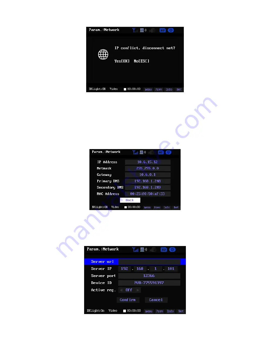
Here you can view the corresponding device network connection information of your setup. See 
Figure 3-27. 


Figure 3-27


3.6.3.6.1.3 Register  

Highlight the Register button and then click the OK, the interface is shown as below. See Figure 
3-28. 


Figure 3-28 

Summary of Contents for PVR210

Page 1: ...1 PVR210 User s Manual Version 1 3 ...

Page 2: ...7 2 Framework 9 2 1 General Structure 9 2 2 Front Panel 9 2 3 Port 10 2 4 Cable Control Introduction 10 3 PVR Interface and Operation 12 3 1 Boot up and Shutdown 12 3 2 Standby and Wake up 12 3 3 Lock Unlock 12 3 4 System Monitor and Management Interface 13 3 5 Record Operation 15 ...

Page 3: ...3 3 6 Main Menu 16 3 6 1 Playback 16 3 6 2 Snapshot 19 3 6 3 Parameter Setup 20 3 6 4 Format 32 3 6 5 Shut Down 33 Appendix Toxic or Hazardous Materials or Elements 34 ...

Page 4: ...uct This user s manual is designed to be a reference tool for the installation and operation of your system Please read the following safeguard and warnings carefully before you use this series product Please keep this user s manual well for future reference ...

Page 5: ...id strike or strong vibration PVR device may be damaged if you use or storage improperly 4 Accessories z Be sure to use all the accessories recommended by the manufacturer z Do not expose the camera to strong light for a long time It may damage the sensitive components such as the CMOS 5 SD card z Please pay attention to SD card installation direction Otherwise it may result in SD card damage or P...

Page 6: ...before you begin recording Warning z Do not dismantle PVR device without authorization z Improper battery use may result in fire explosion or personal injury z When replace the battery please make sure you are using the same model Some functions listed in this user s manual are optional Please make sure you purchased model supports current function before your operation ...

Page 7: ...g period Main unit only For the general device it is about 4 5 hours For the device of the network module it is 2 3 hours Battery capacity threshold alarm When battery left power capacity is less than 10 minutes the buzzer begins beeping regularly to alert you to recharge LCD power management System can automatically shut down LCD power after the PVR stopped operation for specified time such as te...

Page 8: ... control light flashes once in every three seconds z Record status Cable control light is on z Pause status Cable control light flashes once per second z Standby or stop status Cable control lights all become off z Shut down mode Cable control lights all become off Working temperature 0 55 Working humidity 10 90 Dimensions L W H 105mm 75mm 34mm General Parameter Weight 0 14Kg excluding battery and...

Page 9: ...1 2 2 Front Panel Please refer to Figure 2 2 for external keys There are nine keys It includes one power button and eight special keys Figure 2 2 Cable control slot Function key 接口侧盖 Port side cover Chassis bottom cover Battery cover Chassis up cover Record Snapshot OK Right Up Left Down Cancel ...

Page 10: ...t is to provide power to the device z Mini USB port You can connect the device to the PC via this port Figure 2 3 2 4 Cable Control Introduction Please refer to Figure 2 4 for cable control information Cable control sub system includes one camera one microphone two control keys and one status indication light System provides analog audio and video signal input and keystroke control signal input St...

Page 11: ...urface of the lens You can use the dry cloth with some alcohol or mild detergent to clear if necessary z Do not use the volatility solvent such as the benzene or thinner or detergent with strong abradibility It may result in lens damage or it may adversely affect the device performance Cable control buckle Microphone Indication light Off On Camera IR light ...

Page 12: ... the power and reload again 3 2 Standby and Wake up There are two ways for you to let the device standby z When PVR is running properly press the Standby button of the cable control for three seconds you can let the PVR standby You can see standby interface and then system begins three second countdown System stops internal operation such as record or play first and then become standby Before the ...

Page 13: ...mation SN Name Function 1 System time Display system current date and time 2 Network signal It is to display current network signal intensity 3 Network status It is highlighted when the device connected to the network Otherwise it is grey 4 Working status You can see the corresponding icon when the device is playback record or snapshot 5 SD card status This icon is grey when there is no SD card Th...

Page 14: ...it to go to the audio video setting interface chapter 3 6 3 5 15 Information Click it to go to the SD card and GPS information interface z SD card interface is to display the SD card status and capacity See Figure 3 3 z GPS interface is to display the device geographical information See Figure 3 4 16 Net Click it to go to the network setup interface The SD card interface is shown as in Figure 3 3 ...

Page 15: ...erface now See Figure 3 5 You can refer to chapter 3 4 for general interface button information You can refer to the following sheet for detailed information Icon Function When the device is recording press the Record button of the front panel you can pause current record operation You can see the icon at the bottom of the interface In pause status you can click Record button of the cable control ...

Page 16: ...he main menu buttons include playback snapshot parameter and format and shut down You can use Left Right button to highlight the corresponding item and then click the OK button to go to the corresponding interface See Figure 3 6 Figure 3 6 3 6 1 Playback Please highlight the Playback button and then click OK button to go to playback file list interface See Figure 3 7 Figure 3 7 Basic Information I...

Page 17: ...e the deleted file if you remove here Playback control bar During the playback period click OK button for a long time you can see a playback control bar shown as in Figure 3 8 You can click Cancel button for a little bit while or press OK button for a long time to hide the playback control bar Figure 3 8 Figure 3 9 Please refer to the following sheet for detailed information Icon Name Function Det...

Page 18: ...rm Now you can see system is in pause mode When the playback control bar is hidden you can click OK button for a short while to realize pause and restore function Stop Please use click Left or Right button to select to stop playback System goes back to file list interface Figure 3 7 after you stopped playback When the playback control bar is hidden you can press Cancel button for a short while to ...

Page 19: ...with time The latest file is on the top System maximally displays 1024 files in one folder Detailed Operation Please use the left right button to switch between the file folders and file list frame Please use Up and Down to select playback file or folder and then click OK button to go to the file folder or begin the playback Press the OK button for a long time in the image browser interface you ca...

Page 20: ...n You can see the zoom icon at the top right corner after you click this button Detailed information Here is to display the play file basic information Play previous Play next Play the previous file or play the next 3 6 3 Parameter Setup Click OK button to go to main menu highlight parameter item and then click OK to confirm you can go to the parameter setup interface See Figure 3 14 Figure 3 14 3...

Page 21: ...se refer to the following sheet for detailed information Name Function Sleep in battery mode In battery power supply mode system automatically standby time when there is no system operation Exclude record or playback for specified time Standby in DC mode In DC power supply mode system automatically standby time when there is no system operation Exclude record or playback for specified time Backlig...

Page 22: ...firm upgrade Please follow the prompt to click OK button to begin upgrade You can click Cancel button to exit During the upgrade period you can refer to the process bar for reference System needs to restart after completing upgrade Please note during the upgrade period system stops all other operations Warning z Before you upgrade please make sure the battery capacity is sufficient z To guarantee ...

Page 23: ...ain to activate current setup Figure 3 18 Figure 3 19 You can refer to the following sheet for detailed information Name Function Record type There are two types one is with audio video and the other one is with the audio only Audio sampling rate Right now the device support 16K only Audio frame rate There are five options 24k 32k 48k 64k 80k Video resolution There are five options 320 240 640 480...

Page 24: ... frame rate and bit rate will maintain the same Cancel Click it to cancel your current setting Restore Here is to restore main stream factory default setup Click the Restore button you can see the system pops up a dialogue box asking you to restore factory default setup or not Click OK button system will begin restoring Please note if the device is recording system can not restore the factory defa...

Page 25: ...gue box 3 6 3 5 Boot up Interface In Figure 3 14 please use Left and Right button to highlight Boot up Interface item and then click OK button to go to the boot up dialogue box You can set to use your self defined boot up int6erface Click Cancel you can go to the previous interface click Ok you can update the boot up interface Important Before modification Please copy the logo bmp file 16 bit or 2...

Page 26: ...ht the Configure button and then click the OK button the interface is shown as in Figure 3 22 The IP address subnet mask and the default gateway is to display the previous setup information Please click the OK button at the item you want to set you can see the system pops up a dialogue box for you to input the number for the IP address subnet mask default gateway and DNS Click the Input button to ...

Page 27: ...y and then click the OK button to save current setup Figure 3 24 z Connect Click the Connect button in Figure 3 21 to connect to the network You can see the corresponding dialogue box See Figure 3 25 Figure 3 25 System will check the IP conflict occurred or not after WIFI connection You can see the following dialogue box if the IP conflict occurred See Figure 3 26 ...

Page 28: ...he WIF network 3 6 3 6 1 2 Information Here you can view the corresponding device network connection information of your setup See Figure 3 27 Figure 3 27 3 6 3 6 1 3 Register Highlight the Register button and then click the OK the interface is shown as below See Figure 3 28 Figure 3 28 ...

Page 29: ...the system pops up the following dialogue box See Figure 3 29 Please use the direction keys to select the character and then click the OK button to confirm current option You can see the selected character displayed in the No1 position For other input interface you can see a dialogue box on the right pane of the Figure 3 29 Figure 3 29 You can refer to the following sheet for detailed information ...

Page 30: ... Online time Here you can view network connection time You can set the network You do not need to set the IP address Please refer to the following contents for detailed operation information Information You can see current network setup information Register z You can set the setup information so that the device can connect to the corresponding server z Please refer to the following contents for de...

Page 31: ...ly User name and password The user name and password you get from your operator It can be modified if necessary z Connect Click the Connect button in Figure 3 30 to connect to the network You can see the corresponding dialogue box See Figure 3 32 Figure 3 32 If the SIM card is not proper system will display the following dialogue See Figure 3 33 You can see the system can not connect to the 3G net...

Page 32: ...to the register section of the WIFI setup 3 6 4 Format In the main menu select Format item and then click OK button See Figure 3 34 You can go to the format interface Please follow the prompt information to click OK button to begin format process You can click Cancel button to go back to previous interface Figure 3 34 Important All data in the CS card will be removed completely and can not be rest...

Page 33: ...rst and then in the main menu use Left and Right button to highlight Shutdown item and then click OK button to turn off the PVR directly See Figure 3 35 You can press the power button for a long time or cable control key to turn off the PVR Figure 3 35 ...

Page 34: ...of the SJ T11363 2006 standard X Indicates that the concentration of the hazardous substance of at least one of all homogeneous materials in the parts is above the relevant threshold of the SJ T11363 2006 standard Note z This manual is for reference only Slight difference may be found in the user interface z All the designs and software here are subject to change without prior written notice z If ...

Reviews: