


217
Section 1: there are six function buttons: Live
(
chapter 0
)
, setup (chapter 5.8), info (Chapter 5.9),
playback (chapter 5.10), alarm (chapter 5.11), and logout (chapter 5.12).
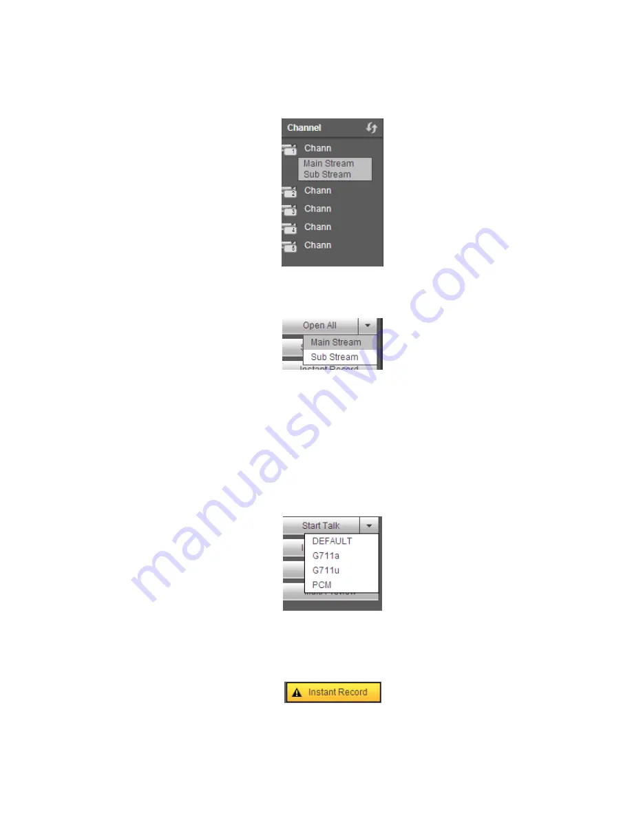
Section 2: There are monitor channels successfully connected to the NVR.
Please refer to Figure 5-4 for main stream and extra stream switch information.
Figure 5-4
Section 3: Open all. Open all button is to enable/disable all-channel real-time monitor. Here you can
select main stream/sub stream too. See Figure 5-5.
Figure 5-5
Section 4: Start Talk button.
You can click this button to enable audio talk. Click
【
▼
】
to select bidirectional talk mode. There are four
options: DEFAULT
,
G711a
,
G711u and PCM. See Figure 5-6.
After you enable the bidirectional talk, the Start talk button becomes End Talk button and it becomes
yellow. Please note, if audio input port from the device to the client-end is using the first channel audio
input port. During the bidirectional talk process, system will not encode the audio data from the 1-channel.
Figure 5-6
Section 5: Instant record button. Click it, the button becomes yellow and system begins manual
record. See Figure 5-7. Click it again, system restores previous record mode.
Figure 5-7
Section 6: Local play button.
Summary of Contents for NVR4108-P
Page 1: ...Network Video Recorder User s Manual V 1 6 0...
Page 39: ...27 Weight 1 5kg 2 5kg Exclude HDD Installation Desk installation...
Page 104: ...92 Figure 3 10 3 5 11 NVR78 Series Please refer to Figure 3 11 for connection sample...
Page 105: ...93 Figure 3 11 3 5 12 NVR78 16P Series Please refer to Figure 3 12 for connection sample...
Page 106: ...94 Figure 3 12 3 5 13 NVR78 RH Series Please refer to Figure 3 13 for connection sample...
Page 107: ...95 Figure 3 13 3 5 14 NVR70 Series Please refer to Figure 3 14 for connection sample...
Page 108: ...96 Figure 3 14 3 5 15 NVR70 R Series Please refer to Figure 3 15 for connection sample...
Page 109: ...97 Figure 3 15 3 5 16 NVR42V 8P Series Please refer to Figure 3 16 for connection sample...
Page 110: ...98 Figure 3 16...
Page 169: ...157 Figure 4 81 Figure 4 82...
Page 170: ...158 Figure 4 83 Figure 4 84...
Page 176: ...164 Figure 4 89 Figure 4 90...
Page 177: ...165 Figure 4 91 Figure 4 92...
Page 178: ...166 Figure 4 93 Figure 4 94...
Page 180: ...168 Figure 4 96 Figure 4 97...
Page 220: ...208 Figure 4 144 Figure 4 145 4 15 3 1 Add Modify Group...
Page 261: ...249 Figure 5 53 Figure 5 54...
Page 262: ...250 Figure 5 55 Figure 5 56 Figure 5 57...
Page 266: ...254 Figure 5 61 Figure 5 62...


