


173
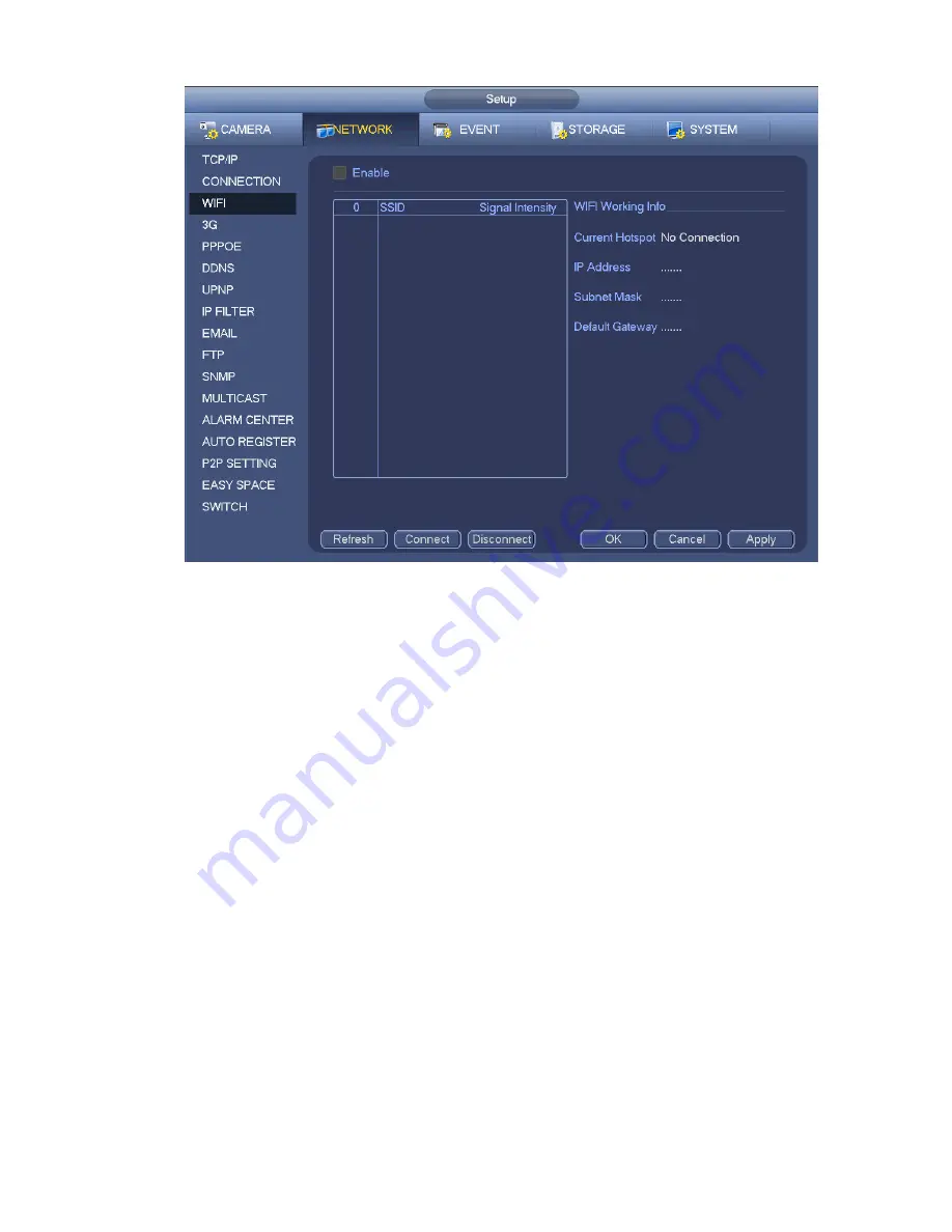
Figure 4-102
WIFI working status: Here you can view current connection status.
Please note:
After successful connection, you can see WIFI connection icon at the top right corner of the preview
interface.
When the hotspot verification type is WEP, system displays as AUTO since the device can not detect
its encryption type.
System does not support verification type WPA and WPA2. The display may become abnormal for
the verification type and encryption type.
After device successfully connected to the WIFI, you can view the hotspot name, IP address, subnet
mask, default gateway and etc. Right now system support TOTOLINK_N2200UP module.
4.12.1.4 3G
3G setup interface is shown as below. See Figure 4-103.
Please refer to the following contents for the parameter information.
Pane 1: Display 3G signal intensity after you enabled 3G function.
Pane 2: Display 3G module configuration information after you enabled 3G function.
Pane 3: Display 3G module status information after you enabled 3G function.
It is to display current wireless network signal intensity such as EVDO, CDMA1x, WCDMA, WCDMA,
EDGE and etc.
3G module: It is to display current wireless network adapter name.
3G Enable/Disable: Check the box here to enable 3G module.
Network type: There are various network types for different 3G network modules. You can select
according to your requirements.
Summary of Contents for NVR4108-P
Page 1: ...Network Video Recorder User s Manual V 1 6 0...
Page 39: ...27 Weight 1 5kg 2 5kg Exclude HDD Installation Desk installation...
Page 104: ...92 Figure 3 10 3 5 11 NVR78 Series Please refer to Figure 3 11 for connection sample...
Page 105: ...93 Figure 3 11 3 5 12 NVR78 16P Series Please refer to Figure 3 12 for connection sample...
Page 106: ...94 Figure 3 12 3 5 13 NVR78 RH Series Please refer to Figure 3 13 for connection sample...
Page 107: ...95 Figure 3 13 3 5 14 NVR70 Series Please refer to Figure 3 14 for connection sample...
Page 108: ...96 Figure 3 14 3 5 15 NVR70 R Series Please refer to Figure 3 15 for connection sample...
Page 109: ...97 Figure 3 15 3 5 16 NVR42V 8P Series Please refer to Figure 3 16 for connection sample...
Page 110: ...98 Figure 3 16...
Page 169: ...157 Figure 4 81 Figure 4 82...
Page 170: ...158 Figure 4 83 Figure 4 84...
Page 176: ...164 Figure 4 89 Figure 4 90...
Page 177: ...165 Figure 4 91 Figure 4 92...
Page 178: ...166 Figure 4 93 Figure 4 94...
Page 180: ...168 Figure 4 96 Figure 4 97...
Page 220: ...208 Figure 4 144 Figure 4 145 4 15 3 1 Add Modify Group...
Page 261: ...249 Figure 5 53 Figure 5 54...
Page 262: ...250 Figure 5 55 Figure 5 56 Figure 5 57...
Page 266: ...254 Figure 5 61 Figure 5 62...


