216
it
to
set
time.
See
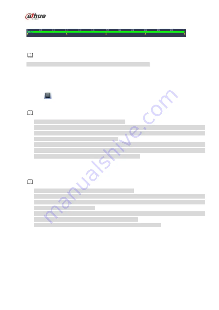
Figure 4-100
Note
Select split mode, so that the record can be spliced in several sections.
Select splice file.
Click Playback, system playbacks from the first of current date by default.
Click time bar, system playbacks from the time you click.
Click
, you can select on the file list.
Note
The splice playback is for 1-window playback mode.
System supports 1/4/8/16-split mode. Slight different may be found here. The 4-channel series
product supports 4-split mode. The 8-channel series product support 8-split mode. The 16-channel
or higher series product supports 16-split mode.
The min period of each section is 5 minutes. For the record is less than 20 minutes, if you select
4-split mode (or more than 4-split mode), system can auto adjust so that the each section period is 5
minutes. In this situation, some channel may have no video.
4.6.7
Smart Playback
It is to search and playback the IVS file, human face file and plate recognition record.
Note
There are two types to realize intelligent analytics function.
Smart network camera supports intelligent functions: Some smart camera supports the intelligent
functions. For NVR, it just displays the intelligent alarm information from the smart network camera
and set or playback the record file.
NVR supports intelligent functions: The connected network camera does not support intelligent video
analytics function. The NVR supports the analytics function.
This function is to playback the intelligent record file of the smart camera.
4.6.7.1 IVS File
It is to search and playback the IVS record file.
Step 1 From main menu->Operation->Smart Play.
Enter the smart play interface. See Figure 4-101.
Summary of Contents for NVR21-S2 SERIES
Page 1: ...Dahua Network Video Recorder User s Manual V 4 3 0...
Page 138: ...124 Figure 3 5 3 6 6 NVR42N Series Please refer to Figure 3 6 for connection sample Figure 3 6...
Page 142: ...128 Figure 3 11 3 6 12 NVR42V 8P Series Please refer to Figure 3 12 for connection sample...
Page 143: ...129 Figure 3 12...
Page 157: ...143 Figure 4 15 Step 2 Click device display edit interface See Figure 4 16...
Page 220: ...206 Figure 4 93 Figure 4 94...
Page 240: ...226 Figure 4 110 Figure 4 111 Figure 4 112...
Page 251: ...237 Figure 4 123 Figure 4 124...
Page 253: ...239 Figure 4 126 Click draw button to draw the zone See Figure 4 127...
Page 257: ...243 Figure 4 130 Click Draw button to draw a zone See Figure 4 131 Figure 4 131...
Page 262: ...248 Figure 4 136 Click draw button to draw the zone See Figure 4 137...
Page 275: ...261 Figure 4 148 Figure 4 149...
Page 276: ...262 Figure 4 150 Figure 4 151...
Page 387: ...373 Figure 5 60 Figure 5 61...
Page 388: ...374 Figure 5 62 Figure 5 63...
Page 412: ...398 Figure 5 96 Figure 5 97...


