background image


12 


Connect the corresponding power, video output, audio cable, RS485 control 

cable, alarm input and output terminal according to requirement, and then 

twine the cable connection location with insulated rubber tape to make it 

waterproof.  

Caution 

The video port is covered the heat shrink tube of high shrinking ratio. After 

the video connection, please heat the tube and wrap it with waterproof tape, 

including other video connection ports. Make sure the video port is damp 

proof and waterproof.   


Connect the network cable to the corresponding network port of device 

according to step 5.  

Note  

It is recommended that the GND hole shall be connected to ground, which is to 

improve device reliability.  

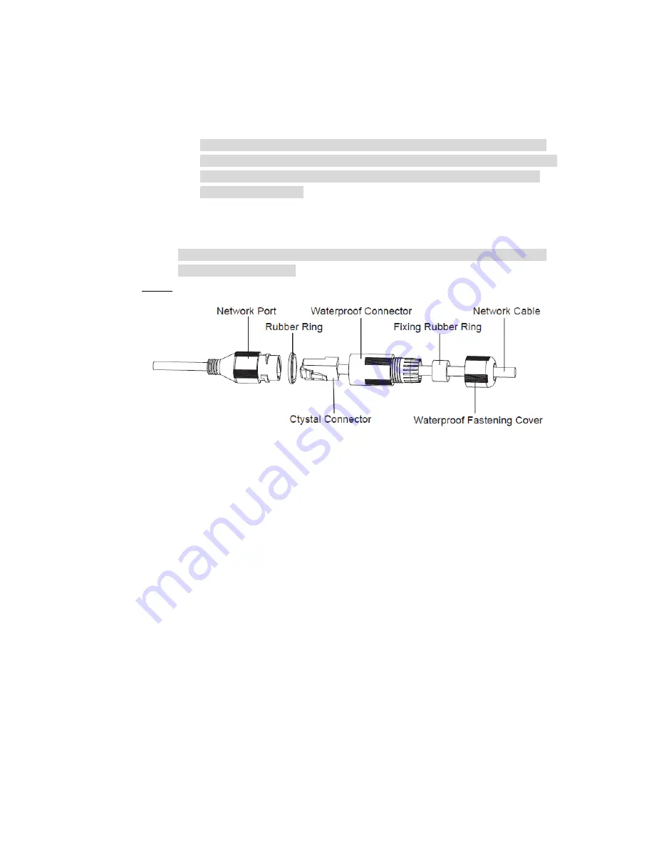
Step 5  Install waterproof connector for network port, which is shown in Figure 2-6. 


Figure 2-6  

1)  Keep the convex groove outward and install the rubber ring into the 

network port, and keep the smaller hole of the rubber ring outward and 

install the fixing rubber ring into the main body of the waterproof connector.  

2)  After pulling the network cable without crystal head through main body of 

waterproof connector, fixing rubber ring and waterproof fastening cover, 

make the crystal connector of network cable and then insert it into the 

network cable.  

3)  Put the main body of waterproof connector on the network port and rotate it 

clockwise to lock the network port and waterproof connector firmly. 

4)  Put the waterproof fastening cover on the main body of waterproof 

connector and rotate it clockwise to lock the waterproof connector and 

waterproof fastening cover firmly. 


Summary of Contents for DH-TPC-PT8320A

Page 1: ...Thermal High Speed Hybrid PTZ Camera Quick Start Guide Version 1 0 0...

Page 2: ...nstallation Environment Do not aim the device at strong light to focus such as lamp light and sun light otherwise it might cause over brightness or light marks which are not the device malfunction and...

Page 3: ...the lens center outward till it is clean We are not liable for any problems caused by unauthorized modification or attempted repair Warnings Please modify the default password after login to avoid be...

Page 4: ...io communication However there is no guarantee that interference will not occur in a particular installation If this equipment does cause harmful interference to radio or television reception which ca...

Page 5: ...evice Installation 8 2 1 Install Micro SD Card and Reset Device 8 2 2 Device Installation Side Cable Exit 9 2 3 Device Installation Bottom Cable Exit 10 3 Network Configuration 13 3 1 Modify IP Addres...

Page 6: ...able ports There might be some minor differences between different devices so please refer to the actual products you purchased Figure 1 1 Thermal hybrid PTZ camera is equipped with a multifunctional...

Page 7: ...485 port RS485 port control PTZ and so on 7 POWER Power input port Input AC 24V please be sure to supply power to the device according to the device label instruction Caution It may cause damage to th...

Page 8: ...7 Refer to Figure 1 3 and Figure 1 4 for the device dimension and pole mounted chassis respectively The unit is mm Figure 1 3 Figure 1 4...

Page 9: ...and Reset Device Caution Micro SD card installation needs to be operated by professional technician the company is not liable to the device malfunction if it is operated unprofessionally Make sure the...

Page 10: ...ing holes of camera through expansion bolts cover it with flat washer and spring washer successively use nut to lock it firmly and fix the device on the cement block stably Step 4 Connect the external...

Page 11: ...dy of waterproof connector on the network port and rotate it clockwise to lock the network port and waterproof connector firmly 4 Put the waterproof fastening cover on the main body of waterproof conn...

Page 12: ...hen lock them firmly Caution It needs to make sure that the sealing gasket is located in the sealing slot which is to avoid water leaking and causing damage to the device Step 2 Pull the cable through...

Page 13: ...eliability Step 5 Install waterproof connector for network port which is shown in Figure 2 6 Figure 2 6 1 Keep the convex groove outward and install the rubber ring into the network port and keep the...

Page 14: ...eters of the WEB interface Please refer to the document WEB Operation Manual for more details To modify IP address do the following Step 1 Double click ConfigTool exe to open the Quick Configuration T...

Page 15: ...3 2 Login WEB Interface Note Different devices might have different WEB interfaces the figures in this document are just for reference please refer to the document WEB Operation Manual and the actual...

Page 16: ...please modify the administrator password as soon as possible after you successfully logged in Step 3 Click Login and the system will display the main interface which is shown in Figure 3 4 Note Please...

Page 17: ...ne point to the earth Open floor cable layout is forbidden In area of strong thunderstorm hit or near high sensitive voltage such as near high voltage transformer substation you need to install additi...

Reviews: