


S0802190K
Page 34
Electrical System
Return to Master Table of Contents
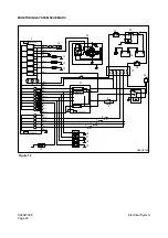
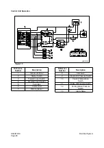
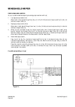
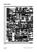
(R)(11) will be turned "ON," and the other current flows to the "CN2-7" terminal of instrument
panel (17) and the headlight indicator will be "ON."
The combination switch (4) is returned automatically.
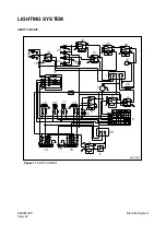
3.
When the combination switch (4) is in the "
←
" (or "
→
") position, the current flows from the fuse box 1
(1), to the blinker unit (2), to the "L" (or "R") terminal through "49a" terminal of combination switch (4),
to the "C" terminal of front combination light (L)(12) and the rear combination light (L)(14) (or to the
front combination light (R)(13) and the rear combination light (R)(15)). This current makes the turn
signal light turn "ON." At the same time the current flows to the "CN2-6" terminal (or to the CN2-8
terminal) of instrument panel and the turn signal light indicator L6 (or L8) will be "ON."
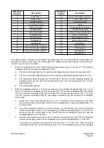
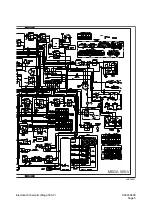
4.
If you operates the hazard light switch (6), the current flows from to the fuse box 1 (1), to the blinker
unit (2), to the "5," "1" terminal of hazard switch (6), to the diode (18), to the front combination light
(L)(12) and the front combination light (R)(13), to the "C" terminal of rear combination light (L)(14)
and rear combination light (R)(15). This current makes the turn signal light turn "ON."
At the same time through the "2," "6" terminal of hazard switch (6), the voltage is applied to the "9"
terminal and the illumination light used to symbol light will be "ON." Also the current flows to the
"CN2-6," "CN2-8" terminal of instrument panel (17) and the turn signal light indicator "L,"" "L8" will be
"ON."
5.
When the shift lever switch (5) is in the "R" position, the contact points "30" and "87" of the reverse
relay (9) are closed due to current flowing from the fuse box 2 (23), to the shift lever switch (5), to the
"86" terminal of reverse relay (9) and to the ground. Thus the current flows from fuse box 2 (23), to
the reverse relay (9) and to the "D" terminal of rear combination light (L)(14) and rear combination
light (R)(15). And the reverse light will be "ON."
6.
When the brake pedal is depressed and at the same time the stop light switch (7) is turned "ON," the
current flows the from fuse box 1 (1), to the stop light switch (7) and to the "F" terminal of rear
combination light (L)(14) and rear combination light (R)(15). And the stop light will be "ON."
7.
When the front working light switch (19) is in the "ON" position, the current flows from the fuse box 1
(1), to the "5," "1" terminal of front working light switch (19) and to the front working light (20).
This current makes the front working lights turn "ON." At the same time the working light indicator,
L9," is turned "ON" due to the current flowing from the diode (8) to the "CN2-9" terminal of instrument
panel (17).
8.
When the rear working light switch (21) is in the second step, the contact points "30" and "87" of the
working light relay (22) is closed due to the flowing current from the fuse box 1 (1), to the "2" and "6"
terminal of the working light switch (21), to the "86" terminal of the working light relay (22) and to the
ground. Thus the current flows from the fuse box 1 (1), to the working light relay (22) and to the rear
working light 1 (23) mounted on radiator guard. As a result the rear working light (23) turns "ON". At
the same time the working light indicator "L9" turns "ON" due to the current flowing from the diode
(18) to the "CN2-9" terminal of the instrument panel.
9.
When the rear working light switch (21) is in the second step, the contact points "30" and "87" of the
working light relay (22) is closed due to the flowing current from the fuse box 1 (1), to the "2" and "6"
and "3" terminal of the working light switch (21), the rear working (23) is operated like being described
above clause "8" and the rear working light (24) mounted on the cabin turns "ON" at the same time.
10.
When the headlight switch (3) is in the first step or in the second step while the starter switch (26) is
in the "OFF" position, the contact point "30," "87" of alarm relay 1 (28) is closed due to the excited
current, which flows to the coil of alarm relay 1 (28) and the pilot buzzer (27) will sound. But when the
headlight switch (3) is in the first step or in the second step while the starter switch (26) is in the "ON"
position, the contact point "3," "87" of alarm relay 2 (29) is closed due to the excited current, which
flows to the coil of alarm relay 2 (29). At the same time the current is not supplied to the "30" terminal
of alarm relay 1 (28) and the pilot buzzer will not sound any more.
Summary of Contents for Mega 500-V
Page 4: ...1SAFETY ...
Page 41: ...1SPECIFICATIONS ...
Page 47: ...S0203070K Page 6 Specifications for Mega 500 V ENGINE PERFORMANCE CURVES AHS3720L Figure 2 ...
Page 55: ...S0203070K Page 14 Specifications for Mega 500 V ...
Page 56: ...1GENERAL MAINTENANCE ...
Page 70: ...S0302000 Page 14 General Maintenance Procedures Return to Master Table of Contents ...
Page 83: ...1UPPER STRUCTURE ...
Page 85: ...S0403040K Page 2 Counterweight TABLE OF CONTENTS Specifications 3 Counterweight 3 ...
Page 87: ...S0403040K Page 4 Counterweight ...
Page 98: ...1LOWER STRUCTURE AND CHASSIS ...
Page 104: ...S0502020K Page 6 Center Joint Articulation Joint ...
Page 105: ...1ENGINE AND DRIVE TRAIN ...
Page 118: ...S0602170K Page 13 Axle ZF AP 420R Figure 9 ...
Page 119: ...S0602170K Page 14 Axle ZF AP 420R ...
Page 121: ...S0602170K Page 16 Axle ZF AP 420R FINAL DRIVE AP 407 409 Figure 10 ...
Page 123: ...S0602170K Page 18 Axle ZF AP 420R AP 411 415 Figure 11 ...
Page 125: ...S0602170K Page 20 Axle ZF AP 420R AP 417 420 Figure 12 ...
Page 129: ...S0602170K Page 24 Axle ZF AP 420R Differential Carrier RK Figure 14 ...
Page 131: ...S0602170K Page 26 Axle ZF AP 420R Differential Carrier DK ...
Page 135: ...S0602170K Page 30 Axle ZF AP 420R Differential Carrier HK Figure 16 ...
Page 178: ...S0602170K Page 73 Axle ZF AP 420R ILLUSTRATED TABLE Figure 152 ...
Page 194: ...S0602170K Page 89 Axle ZF AP 420R ILLUSTRATED TABLE Figure 196 ...
Page 210: ...S0602170K Page 105 Axle ZF AP 420R ILLUSTRATED TABLE Figure 242 ...
Page 225: ...S0602170K Page 120 Axle ZF AP 420R ILLUSTRATED TABLE Figure 289 ...
Page 251: ...S0605050K Page 26 Air Conditioner Return to Master Table of Contents ...
Page 261: ...S0607080K Page 10 Transmission and Torque Converter ZF 4WG 310 Figure 2 ...
Page 264: ...S0607080K Page 13 Transmission and Torque Converter ZF 4WG 310 ...
Page 271: ...S0607080K Page 20 Transmission and Torque Converter ZF 4WG 310 ...
Page 296: ...S0607080K Page 45 Transmission and Torque Converter ZF 4WG 310 ...
Page 447: ...S0607900C Page 36 Transmission Error Codes ZF ...
Page 448: ...1HYDRAULICS ...
Page 478: ...S0705010 Page 22 Cylinders Return to Master Table of Contents ...
Page 489: ...S0708460K Page 11 Main Pump Denison T6DMY Series ...
Page 490: ...S0708460K Page 12 Main Pump Denison T6DMY Series PARTS LIST Figure 8 ...
Page 504: ...S0708460K Page 26 Main Pump Denison T6DMY Series ...
Page 508: ...S0708470K Page 4 Steering and Brake Pump Denison T67DB Series PARTS LIST Figure 2 ...
Page 514: ...S0708470K Page 10 Steering and Brake Pump Denison T67DB Series DISASSEMBLY Figure 5 ...
Page 521: ...S0708470K Page 17 Steering and Brake Pump Denison T67DB Series ...
Page 522: ...S0708470K Page 18 Steering and Brake Pump Denison T67DB Series REASSEMBLY Figure 15 ...
Page 528: ...S0708470K Page 24 Steering and Brake Pump Denison T67DB Series ...
Page 548: ...S0709476K Page 2 Pilot Control Valve Return to Master Table of Contents ...
Page 554: ...S0709476K Page 8 Pilot Control Valve Return to Master Table of Contents ...
Page 557: ...S0709665K Page 3 Flow Amplifier Danfoss GENERAL DESCRIPTION Figure 1 ...
Page 558: ...S0709665K Page 4 Flow Amplifier Danfoss PARTS LIST Figure 2 ...
Page 609: ...S0709730K Page 7 Power Steering Unit Return to Master Table of Contents ...
Page 632: ...S0709730K Page 30 Power Steering Unit Return to Master Table of Contents ...
Page 638: ...S0709750K Page 6 Restriction Valve Return to Master Table of Contents ...
Page 644: ...S0793060K Page 6 Hydraulic Schematic Mega 500 V Return to Master Table of Contents ...
Page 645: ...1ELECTRICAL SYSTEM ...
Page 654: ...S0802190K Page 9 Electrical System Return to Master Table of Contents ...
Page 658: ...S0802190K Page 13 Electrical System Return to Master Table of Contents ...
Page 676: ...S0802190K Page 31 Electrical System Return to Master Table of Contents ...
Page 685: ...S0893060K Page 6 Electrical Schematic Mega 500 V Return to Master Table of Contents ...
Page 686: ...1ATTACHMENTS ...


