"
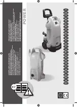
Operating Mechanism Diagram
6
4. WATER SUPPLY PART
• Cold Water: 3 holes
Cold water, pre-washing
• Hot Water: 1 hole
• Water supply box, hose
5. DOOR
• Door lock S/W
- Lock hinge
• Door AS: Glass
• Gasket
6. DRAINAGE PART
• Drainage pump
• Valve housing
• Hose
7. SUPPORTER
• Base
• Damper AS: 4
• Spring: 2
3. HEATING PART
• Water Heater: 1000W
• Washing temperature
sensor
2. DRIVING PART
• BLDC motor
• Drum
• Bearing
• Spider/ shaft
• Tub
• Weight balancer
1. CONTROL PART
• Main PCB
• Front PCB
• Harness
• Noise filter
• Power Cord: 15A
4. WATER SUPPLY PART
• Cold Water: 3 holes
Cold water, pre-washing
• Hot Water: 1 hole
• Water supply box, hose
Water
Supply
Delergent
Container
Thermister
Door
Door
Switch
Drainage
Pump
Washing
Heater
Thermister
BLDC
Motor
Drum
Program
Electricity Input
Noise Filter
5. DOOR
• Door lock S/W
• Lock hinge
• Door AS: Glass
• Gasket
6. DRAINAGE PART
• Drainage pump
• Valve housing
• Hose
7. SUPPORTER
• Base
• Damper AS: 4
• Spring: 2
3. HEATING PART
• Water Heater: 1000W
• Washing temperature
sensor
2. DRIVING PART
• BLDC motor
• Drum
• Bearing
• Spider/ shaft
• Tub
• Weight balancer
1. CONTROL PART
• Main PCB
• Front PCB
• Harness
• Noise filter
• Power Cord: 15A
Summary of Contents for DWD-WD135 SERIES
Page 48: ...47 PCB PIN ARRANGEMENT ...
Page 60: ...59 BLDC Motor Power Transmission System of BLDC Motor ...
Page 65: ...64 Wiring Diagram ...
Page 71: ...70 PLATE TOP ASS Y 1 Remove 3 screws 2 Remove 4 screws ...
Page 73: ...72 VALVE 3WAY 1 Remove 4 screws 2 Separate 3 connectors 3 Separate 3 hose clamps ...