


43
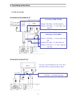
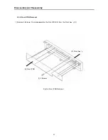
1) Remove 2 Screws (1) on the back of the Cabinet.
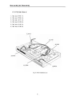
2) Remove 8 Screws (2) and disassemble the Main PCB (3) and SMPS PCB (4).
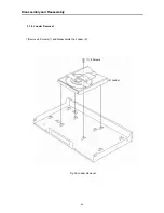
3) Remove 6 Screws (5) and disassemble the Front Ass’y (6).
5-1-4 PCB and Front Ass’y Removal
(2) 8 Screws
(1) 2 Screws
(4) SMPS PCB
(3) Main PCB
(6) Front Ass’y
Fig 5-4 PCB and Front Ass’y Removal
Disassembly and Reassembly
(5) 6 Screws
Summary of Contents for DVC-T6300N
Page 10: ...10 2 1 3 NTSC PAL Digital Video Encoder AD7170 Component Descriptions ...
Page 11: ...11 Component Descriptions ...
Page 12: ...12 Component Descriptions ...
Page 14: ...14 Functional Description Component Descriptions ...
Page 15: ...15 Component Descriptions Pinout Diagram ...
Page 18: ...18 Block Diagram Component Descriptions 2 1 5 DIGITAL TO ANALOG STEREO AUDIO CONVERTER CS4391 ...
Page 19: ...19 Component Descriptions ...
Page 20: ...20 Component Descriptions ...
Page 21: ...21 Component Descriptions ...
Page 28: ...28 Component Descriptions ...
Page 30: ...30 Component Descriptions ...
Page 31: ...31 Component Descriptions ...
Page 54: ...54 9 PCB Diagrams 9 1 Main PCB Top ...
Page 55: ...55 PCB Diagrams 9 2 Main PCB Bottom ...
Page 56: ...56 9 3 Front PCB Top 9 4 Front PCB Bottom PCB Diagrams ...
Page 57: ...57 9 5 SMPS PCB Top 9 6 SMPS PCB Bottom PCB Diagrams ...
Page 58: ...58 10 Wiring Diagram ...
Page 65: ...65 11 3 SMPS PCB Schematic Diagram 11 3 SMPS PCB Schematic diagram ...
Page 66: ...66 1 27MHz 2 ROM DATA BUS 3 RAM DATA BUS 4 12C CLK 5 12C DATA 6 HSYNC 12 Oscillograms ...
Page 67: ...67 7 VSYNC 8 BCLK DVD 9 LRCK DVD 10 TSDO 11 MCLK 12 HOST DATA Oscillograms ...
Page 68: ...68 13 HOST CLK 14 HOST CS 15 MC DACO 16 MD DACO 17 VFD DATA 18 VFD STB Oscillograms ...
Page 70: ...70 MEMO ...