


4
CAUTION :
Before servicing Instruments covered
by this service manual and its supplements, read
and follow the Safety Precautions section of this
manual.
Note :
If unforeseen circument create conflict
between the following servicing precautions and
any of the safety precautions, always follow the
safety precautions. Remember: Safety First.
1-2-1 General Servicing Precautions
(1) a. Always unplug the instrument’s AC power
cord from the AC power source before (1) re-
moving or reinstalling any component, circuit
board, module or any other instrument
assembly, (2) disconnecting any instrument
electrical plug or other electrical connection,
(3) connecting a test substitute in parallel with
an electrolytic capacitor in the instrument.
b. Do not defeat any plug/socket B+ voltage
interlocks with which instruments covered by
this service manual might be equipped.
c. Do not apply AC power to this instrument
and /or any of its electrical assemblies unless
all solid-state device heat sinks are correctly
installed.
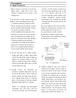
d. Always connect a test instrument’s ground
lead to the instrument chassis ground before
connecting the test instrument positive lead.
Always remove the test instrument ground lead
last.
Note :
Refer to the Safety Precautions section
ground lead last.
(2) The service precautions are indicated or printed
on the cabinet, chassis or components. When
servicing, follow the printed or indicated service
precautions and service materials.
(3) The components used in the unit have a
specified flame resistance and dielectric
strength.
When replacing components, use components
which have the same ratings. Components I-
enti-fied by shading, by ( ) or by ( ) in the
circuit diagram are important for safety or for the
characteristics of the unit. Always replace them
with the exact replacement components.
(4) An insulation tube or tape is sometimes used
and some components are raised above the
printed wiring board for safety. The internal
wiring is sometimes clamped to prevent contact
with heating components. Install such elements
as they were.
(5) After servicing, always check that the removed
screws, components, and wiring have been
installed correctly and that the portion around
the serviced part has not been damaged and so
on. Further, check the insulation between the
blades of the attachment plug and accessible
conductive parts.
1-2-2 Insulation Checking Procedure
Disconnect the attachment plug from the AC outlet
and turn the power ON. Connect the insulation
resistance meter (500V) to the blades of the
attachment plug. The insulation resistance between
each blade of the attachment plug and accessible
conductive parts(see note) should be more than 1
Megohm.
Note :
Accessible conductive parts include metal
panels, input terminals, earphone jacks, etc.
1-2 Servicing Precautions
Summary of Contents for DVC-T6300N
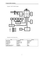
Page 10: ...10 2 1 3 NTSC PAL Digital Video Encoder AD7170 Component Descriptions ...
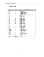
Page 11: ...11 Component Descriptions ...
Page 12: ...12 Component Descriptions ...
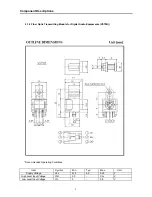
Page 14: ...14 Functional Description Component Descriptions ...
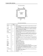
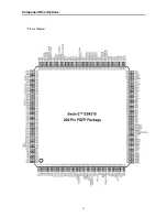
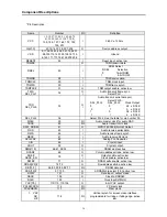
Page 15: ...15 Component Descriptions Pinout Diagram ...
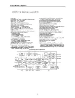
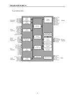
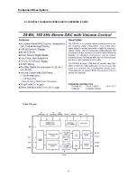
Page 18: ...18 Block Diagram Component Descriptions 2 1 5 DIGITAL TO ANALOG STEREO AUDIO CONVERTER CS4391 ...
Page 19: ...19 Component Descriptions ...
Page 20: ...20 Component Descriptions ...
Page 21: ...21 Component Descriptions ...
Page 28: ...28 Component Descriptions ...
Page 30: ...30 Component Descriptions ...
Page 31: ...31 Component Descriptions ...
Page 54: ...54 9 PCB Diagrams 9 1 Main PCB Top ...
Page 55: ...55 PCB Diagrams 9 2 Main PCB Bottom ...
Page 56: ...56 9 3 Front PCB Top 9 4 Front PCB Bottom PCB Diagrams ...
Page 57: ...57 9 5 SMPS PCB Top 9 6 SMPS PCB Bottom PCB Diagrams ...
Page 58: ...58 10 Wiring Diagram ...
Page 65: ...65 11 3 SMPS PCB Schematic Diagram 11 3 SMPS PCB Schematic diagram ...
Page 66: ...66 1 27MHz 2 ROM DATA BUS 3 RAM DATA BUS 4 12C CLK 5 12C DATA 6 HSYNC 12 Oscillograms ...
Page 67: ...67 7 VSYNC 8 BCLK DVD 9 LRCK DVD 10 TSDO 11 MCLK 12 HOST DATA Oscillograms ...
Page 68: ...68 13 HOST CLK 14 HOST CS 15 MC DACO 16 MD DACO 17 VFD DATA 18 VFD STB Oscillograms ...
Page 70: ...70 MEMO ...


