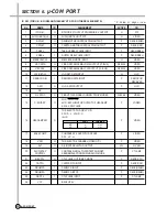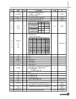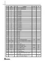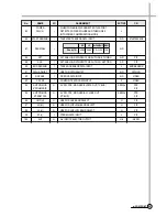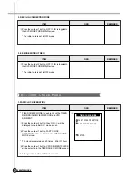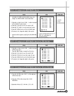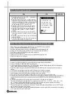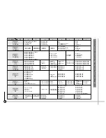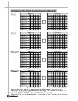
ITEM
1
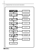
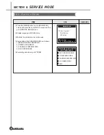
Press the [MENU] button to go to [MAIN MENU]
screen and press the number 484 in sequence then
go to [SERVICE MODE] screen.
2
Display language is ENGLISH only.
3
Maintain the selected mode continuously.
4
Composition of the SERVICE MODE is as follows.
1) SERVICE MODE FOR REPAIR
2) TIMER CHECK MODE
3) CHANGE OF EEPROM DATA
4) Hi-Fi CHECK MODE
5
Everlasting data memory at E
2
PROM
OSD
REMARKS
1
61
SERVICE MODE
SECTION 8.
SERVICE MODE
8-1. Service Mode
➔
Timer Program
Timer Review
VCR Setup
MAIN MENU
PR+/-:select
OK :confirm MENU:end
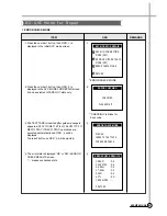
1
SVC MODE FOR REPAIR
2
TIMER CHECK MODE
3
CHANGE OF EEPROM DATA
4
Hi-Fi CHECK MODE
0
EXIT
WELCONE TO SVC MODE!
(M37775M7H-146GP)
Summary of Contents for DV-K88 series
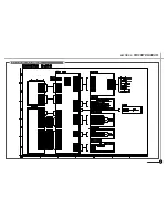
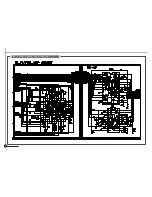
Page 71: ...68 CIRCUIT DIAGRAMS 9 1 Connection Diagram SECTION 9 CIRCUIT DIAGRAM 68...
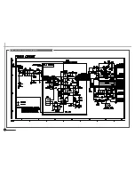
Page 72: ...69 CIRCUIT DIAGRAMS R819 5 1 9 2 Power Circuit Diagram...
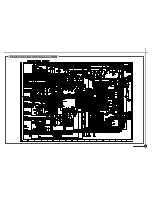
Page 73: ...70 CIRCUIT DIAGRAMS 9 3 Syscon and Logic Circuit Diagram...
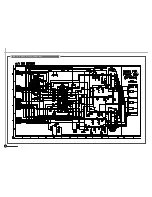
Page 74: ...71 CIRCUIT DIAGRAMS 9 4 AV SW Circuit Diagram...
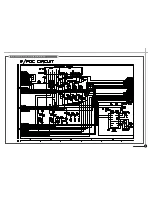
Page 75: ...72 CIRCUIT DIAGRAMS 9 5 IF PDC Circuit Diagram TM...
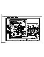
Page 76: ...73 CIRCUIT DIAGRAMS 9 6 If Module Circuit Diagram A2...
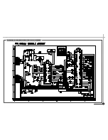
Page 77: ...74 CIRCUIT DIAGRAMS 9 7 If Module Circuit Diagram Nicam...
Page 78: ...75 CIRCUIT DIAGRAMS 9 8 Hi Fi Pre Amp Circuit Diagram...
Page 79: ...76 CIRCUIT DIAGRAMS 9 9 Video Audio Circuit Diagram...
Page 80: ...77 CIRCUIT DIAGRAMS 9 10 Remocon Circuit Diagram...
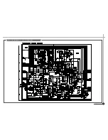
Page 81: ...SECTION 10 COMPONENTS LOCATION GUIDE ON PCB BOTTOM VIEW 78 P C B LOCATION 10 1 PCB Main...
Page 82: ...80 P C B LOCATION 10 3 PCB Logic DV K8K S S Series DV K86 S S Series DV K82 S S Series...
Page 83: ...81 P C B LOCATION DV K88 S S Series...
Page 84: ...SECTION 11 DISASSEMBLY 83 DISASSEMBLY 11 1 Packing Ass y...
Page 85: ...84 DIAGRAMS DV K88 Series DV K82 Series DV K8K Series DV K86 Series 11 2 Front Panel Assembly...

