


18
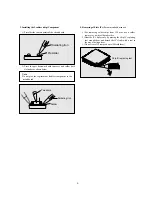
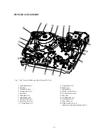
Front Loading Mechanism Removal
(Fig. 12)
NOTE:
The front loading mechanism must be in the eject position to
remove it.
1. Remove two (2) screws holding the Front Loading Mecha-
nism.
2. Lift the rear of the cassette loading mechanism
(hole parts for screw) to separate it from the Main Base.
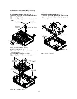
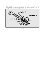
Front Loading Mechanism Disassembly
(Fig. 13~ 17)
1. Remove the front loading mechanism.
2. Remove one (1) screw holding the F/L bracket R and move
the F/L bracket R in the direction of arrow to separate it from
the top plate and the cassette holder assembly.
3. Remove the cassette holder assembly (Fig. 13).
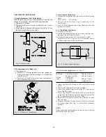
4. Remove one (1) screw holding the prism link R and remove
the prism link R from the F/L bracket R (Fig. 14).
5. Remove one (1) screw holding the prism link L (Fig. 15).
6. Release hook B by pushing it in the direction of the arrow and
remove the door opener (Fig. 15).
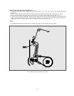
7. Press the linked section of the loading lever assembly in the
direction of the arrow and remove the loading lever assembly
(Fig. 16).
8. Remove the safety spring between the safety lever and the
cassette holder (Fig. 16).
9. Remove the release spring between the relelase lever and the
safety lever R (Fig. 16).
MECHANICAL DISASSEMBLY (Continued)
Fig. 12- Front Loading Mechanism Removal
Fig. 14 - F/L Brkt Disassembly
Fig. 15- Top Plate Disassembly
Fig. 13 - Front loading mechanism disassembly
Summary of Contents for DV- K504N-SJ
Page 35: ...34 AC001 K584NZ SJ M K584NZ SG M only...
Page 36: ...35...
Page 37: ...36...
Page 38: ...37...
Page 39: ...38...
Page 60: ...59 ELECTRICAL ADJUSTMENTS Fig 1 Circuit Board Location...
Page 92: ...91 INTERCONNECT WIRING DIAGRAM K584N K484N K384N K284N...
Page 93: ...92 POWER SUPPLY SCHEMATIC DIAGRAM FREE VOLTAGE K584NY SJ M K584NZ SJ M K584NZ SG M...
Page 95: ...94 2HD HEAD AMP SCHEMATIC DIAGRAM K384N K284N K304N...
Page 96: ...95 4HD HEAD AMP SCHEMATIC DIAGRAM K584N K484N K504N...
Page 97: ...96 VIDEO AUDIO SCHEMATIC DIAGRAM K584N K484N K384N K284N K504N K304N...
Page 98: ...97 PIF INPUT SELECTOR SCHEMATIC DIAGRAM 9V USE K584NY SJ M K584NZ SJ M K584NZ SG M...
Page 100: ...99 TIMER SYSCON SCHEMATIC DIAGRAM K584N K484N K384N K284N K504N K304N...
Page 101: ...100 POWER SUPPLY BLOCK DIAGRAM FREE VOLTAGE K584NY SJ M K584NZ SJ M K584NZ SG M...
Page 103: ...102 2HD HEAD AMP BLOCK DIAGRAM K384N K284N K304N...
Page 104: ...103 4HD HEAD AMP BLOCK DIAGRAM K584N K484N K504N...
Page 105: ...104 VIDEO AUDIO BLOCK DIAGRAM K584N K484N K384N K284N K504N K304N...
Page 106: ...105 PIF INPUT SELECTOR BLOCK DIAGRAM K584N K484N K384N K284N K504N K304N...
Page 109: ...108 MAIN PCB 2HEAD 4HEAD...