14
CIRCUIT OPERATIONAL DESCRIPTION
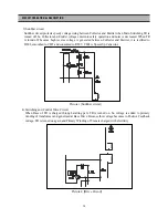
Picture
3 [
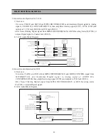
Sunbber circuit
]
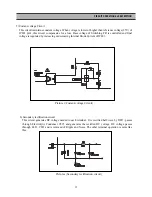
3) Sunbber circuit
Sunbber circuit protects speedy voltage rising between Collector and Emitter when Main Switching TR is
turned off. So Collector and Emitter voltage enter into safety operation and noise is decreased. When TR
is turnd off, because high reverse voltage is generated between Collector and Emitter, it is rectified to
D802, smoothed to C807 and consumed to R809. C808 is Speed-Up Capacitor.
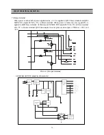
4) Switching and Control Drive Circuit
When Base of TR is charged through starting part, TR is turned on. So voltage is added to primary
winding of transformer and genertaed at Base Drive. Because this voltage becomes to Positive Feedback
voltage, TR is turned on again and Primary Winding of Trans is charged with electricity .
Picture 4 [Drive Circuit]
Summary of Contents for DQD-2100D
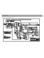
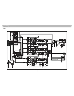
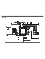
Page 5: ...4 CIRCUIT DIAGRAM POWER SUPPLY SCHEMATIC DIAGRAM DQD 6100 220V ...
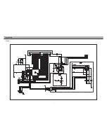
Page 6: ...5 CIRCUIT DIAGRAM VIDEO ...
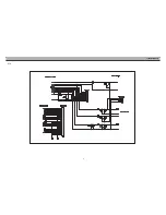
Page 7: ...6 CIRCUIT DIAGRAM AUDIO ...
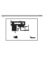
Page 8: ...7 CIRCUIT DIAGRAM VFD JOG ...
Page 9: ...8 CIRCUIT DIAGRAM ETC ...
Page 10: ...9 CIRCUIT DIAGRAM VCR_INT DVD ...
Page 11: ...10 CIRCUIT DIAGRAM ATAPI DVD ...
Page 12: ...11 CIRCUIT DIAGRAM CPU ZR36703 DVD ...
Page 13: ...12 CIRCUIT DIAGRAM MPEG DECODER ...
Page 46: ...45 COMPONENTS LOCATION GUIDE ON PCB BOTTOM VIEW ...
Page 47: ...46 JOG COMPONENTS LOCATION GUIDE ON PCB BOTTOM VIEW M P E G ...
Page 48: ...47 DISASSEMBLY ...
Page 49: ...48 DISASSEMBLY ...
Page 50: ...49 DISASSEMBLY ...
Page 51: ...50 DISASSEMBLY ...


