15
CIRCUIT OPERATIONAL DESCRIPTION
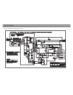
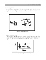
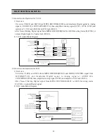
5) Costant-voltage Circuit
This circuit maintains constant voltage. When voltage is lower or higher than reference voltage(2.5V) of
IC801 pin1, this circuit compensates for a loss. Base voltage of Switching TR is controlled and final
voltage is regulated by increasing or decreasing Internal Diode Current of IC801.
Picture
5 [
Costant-voltage Circuit
]
6) Secondary rectification circuit
This circuit generates DC voltage needed to each terminal. It is rectified half-wave by D821, passes
through Electrolytic Condenser C825 and generates the rectified DC voltage. DC voltage passes
through L821, C822 and is removed of Ripple and Noise. The other terminal operation is same like
this.
Picture
6 [
Secondary rectification circuit
]
Summary of Contents for DQD-2100D
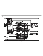
Page 5: ...4 CIRCUIT DIAGRAM POWER SUPPLY SCHEMATIC DIAGRAM DQD 6100 220V ...
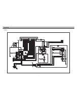
Page 6: ...5 CIRCUIT DIAGRAM VIDEO ...
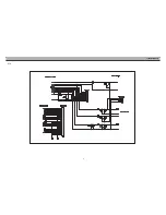
Page 7: ...6 CIRCUIT DIAGRAM AUDIO ...
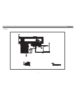
Page 8: ...7 CIRCUIT DIAGRAM VFD JOG ...
Page 9: ...8 CIRCUIT DIAGRAM ETC ...
Page 10: ...9 CIRCUIT DIAGRAM VCR_INT DVD ...
Page 11: ...10 CIRCUIT DIAGRAM ATAPI DVD ...
Page 12: ...11 CIRCUIT DIAGRAM CPU ZR36703 DVD ...
Page 13: ...12 CIRCUIT DIAGRAM MPEG DECODER ...
Page 46: ...45 COMPONENTS LOCATION GUIDE ON PCB BOTTOM VIEW ...
Page 47: ...46 JOG COMPONENTS LOCATION GUIDE ON PCB BOTTOM VIEW M P E G ...
Page 48: ...47 DISASSEMBLY ...
Page 49: ...48 DISASSEMBLY ...
Page 50: ...49 DISASSEMBLY ...
Page 51: ...50 DISASSEMBLY ...

